

What is COB light? – All about COB LED
COB light and SMD LED are the two major sources of light nowadays.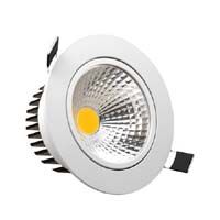 These both device produce high-quality light and have high life expectancy along with the best efficiency till this date.
As we know that light-emitting diode is a newer technology with the advantage of high output corresponding to its input power and of very long life (almost 10 times). Technology is flawless as compared to the older traditional lighting such as fluorescent light which player inefficient and larger in size.
COB LEDs are relatively newer in the LED market and have many advantages over the traditional options. It has a lot of names like flood lamps, downlights, focus lamp, etc.
What is COB light?
LED chips mounted on a single board to act as a source of light is known as COB light. It is also termed as COB LEDs. The COB light’s full form is Chip On Board lights.
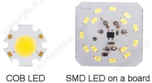
It is a chip made up of small diode combined in parallel and series to form a chip that is capable of giving a high concentration of light called a high luminous intensity chip. Look at the image showing multiple small LED diodes on a single large chip.

On the contrary, SMD LEDs are the device having few diodes in it and having a lower output capacity of light.
COB is a modified form of SMD LED. SMD led is a surface mount LED diode and it is capacity wise just a smaller version of COB.
You can say that cob is a collection of lots of LED diodes integrated into one place.(above image)
What is the need of cob lights?
If we have SMD-LED then why we need COB led? This might be the question arising in your mind. The main reason is output Lux and power handling capacity of the device structure.
Some cob light comes with the wide-angle projection that is used to divert light all over the area, which causes an increase in the efficiency.
On the contrary, SMD LED when mounted on a PCB requires an external diffuser which causes the loss of energy when a light beam is passed through who this diffuser cover.
It is manufactured such that the handling and installing become easier and comes with the large beads/ pin.
Suppose we required ~5000 lumens then, we can use a single 10W cob LED instead of using 15 numbers of 1W SMD.
Advantage of cob LED:
- High lumens (more than 1.5× SMD) from 150 lm/watt @350mA to 250 lm/watt @ 20mA.
- High light concentration due to multi-diode integration.
- Compact in size due to the fact that the light-emitting area is reduced. Which as a result, greatly increases lumen per square centimeter/ inches.
- The lower overall operating temperature of the whole assembly due to ease of installation in an external heat sink. Lifespan and reliability are improved when maintained at a certain temperature, which eventually means money savings for you.
- Large focusing area, as it can cover a large area with a single chip.
- The decrease in the loss of light due to the use of a clear lens. Enhances clarity and contributes to increased efficiency.
Application:
The possibilities for COB LEDs made it a wide range application device from household uses to industrial utilities, some of them are:
- The wide-angle beam made them useful in LED lighting fixtures for installation in living rooms, and large halls.
- High-bay lighting, street lights, and downlights.
- In a large stadium, playground, gardens which require high lumens at night time.
Disadvantage:
- Reduced repairability of lighting fixtures that uses cob chip. This is due to the fact that if any of the single diodes in a whole COB is damaged due to some technical failure then, the complete COB led has to be replaced with the newer one.
But in the case of SMD LED, if any of them undergo a failure then it is easy to replace and get it back to work with less cost. - The requirement of the properly designed heat sink. If the heat sink is not properly installed then due to overheating the diode will be blown. A large amount of heat is generated due to highly concentrated light waves emanating from a small area.
- The well-engineered external power supply as it needs constant current and voltage because any spike in supply can damage the diodes.
- Costlier than SMD chips.
Difference between COB LED and SMD LED:
Table showing COB light vs SMD lights:
| COB LED | SMD LED | |
|---|---|---|
| Output lumen (lm/watt) | 150 lm/watt @350mA to 250 lm/watt @ 20mA | ~100 lm/ watt @300mA |
| Efficiency | Higher | Lower |
| Mounting difficulty | Easy | Moderate to Hard |
| Cost | Expensive | Moderately lower than Cob led's |
| External power Supply | External power supply with high current capability is must | Lower current capability is required |
| Heat sink | Larger heat sink with cooling fan is must due to heavy heat dissipation | Smaller heat sink will work. |
What is an LED driver?
The LED driver is nothing but an external power supply used for powering an LED. This is a fully regulated DC power supply unlike household AC power supply 120V/ 230V.
The external power supply which drives LED are termed as LED drivers. They convert the high alternating voltage to lower DC voltage so as to power LEDs.
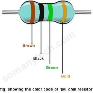


 You do not need to worry about it, just use 510 ohm resistor instead. Because the nearest standard value (to the 500-ohm resistor) is 510 Ohm.


