How to Calculate Voltage Drop Across Resistor Step by Step
Understanding how to calculate voltage drop across a resistor is very fundamental for anyone who is into electronics or electrical engineering. In this step-by-step guide, we will break down the process, making it accessible and very simple even for beginners. By the end, you’ll have a solid grasp of this crucial concept, enabling you to analyze, solve and design circuits with confidence.
Before that let’s brush up the concept of Ohm’s law:
- A common way to show the behavior of a circuit device is it’s characteristic.
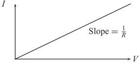
This is a graph of the current “I” through the device as a function of applied voltage “V” across it. This device, the resistor, has the simple linear V– I characteristic shown in fig. above.- This linear relationship of the device is expressed by Ohm’s Law:
V = IR - Here, the constant of proportionality R, is known as the resistance of the device and is equal to the slope of the I–V characteristic. The unit of resistance is ohm, the symbol is Ω. Any device with a linear VI characteristic could be treat as resistive in nature.
What is the voltage drop across a resistor?
- The voltage drop across a resistor is nothing but the voltage value across a resistor. Sometimes it is also called ‘voltage over the resistor’ or simply ‘Voltage drop’.
- It is generally indicated as: ‘V(drop)‘ or ‘Vr’ or ‘Vd’
For multiple resistors, it is written as Vr1, Vr2, Vr3, and so on.
As we all know, a resistor is a device that offers resistance to the current flowing through it. Then, by applying Ohm’s law, the resistor will offer a voltage drop across a resistive device and it is given as:
V(drop) = I × R
where,
I = current through the resistor in (A) ampere
R = resistance in (Ω) ohms
V(drop) = voltage drop in (V) volts
How to calculate voltage drop over resistance step-wise :
Step1: Simplify the given circuit. If the circuit is full of resistors in series and parallel, then rearrange the resistors to make it appear simple connections. (check the practical example below)
Step2: Then, find the equivalent resistance.
For parallel use this formula: 1 / Req. = 1 / R1 + 1 / R2 …
And for series use this: Req. = R1 + R2 + . . .
Step3: Find the current through each resistor. (Current through the series resistor is same and current through the parallel resistors is different and depends on its value)
Step4: Apply the formula from Ohm’s law to calculate voltage drop, V=IR
One way is to check this link –> Voltage Drop Across Resistor Calculator online tool.
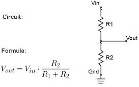
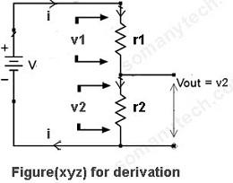
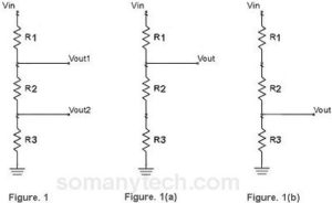
There is also another way to find the voltage drop, simply you can calculate it by using Voltage Divider Formula
The voltage across series circuit- Practical examples:
Case I:
If there is only one resistor in series with a battery or a power supply as shown in this circuit.

In this circuit, the voltage drop across the resistor is the same as that of power supply. This is because both the components have common potential points shared between them (point A & point B)
∴Vs = Vdrop = 5 volts (say)
Case II:
If there are two or more resistors in series with a battery as shown in this circuit.
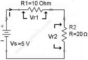
In this circuit, we have to calculate the total current ‘I’ through the circuit.
I (total) = V(supply) / R(equivalent)
∴ I(total) = 5 / 30 =0.166 A
Then, the Voltage drop across R1 will be: Vr1 = I × R1
The voltage drop across R2 will be: Vr2 = I × R2
Also, voltage drop across Rn will be: Vrn = I × Rn
—> Vr1 =I × R1 = 0.166 × 10 =1.66 volts & Vr2 = I × R2 = 0.166 × 20 = 3.33 volts
The voltage across parallel resistors:
Case I:
There are two resistors in parallel with a battery or a power supply as shown in this circuit.
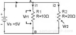
In this circuit, the voltage drop across these parallel resistors is the same as that of power supply.
This is because both the resistors have common potential points shared between them (point A & point B), so the voltage will be the same but the current will be different.
∴Vs = Vdrop = Vr1 = Vr2 = 5 volts (say)
Case II:
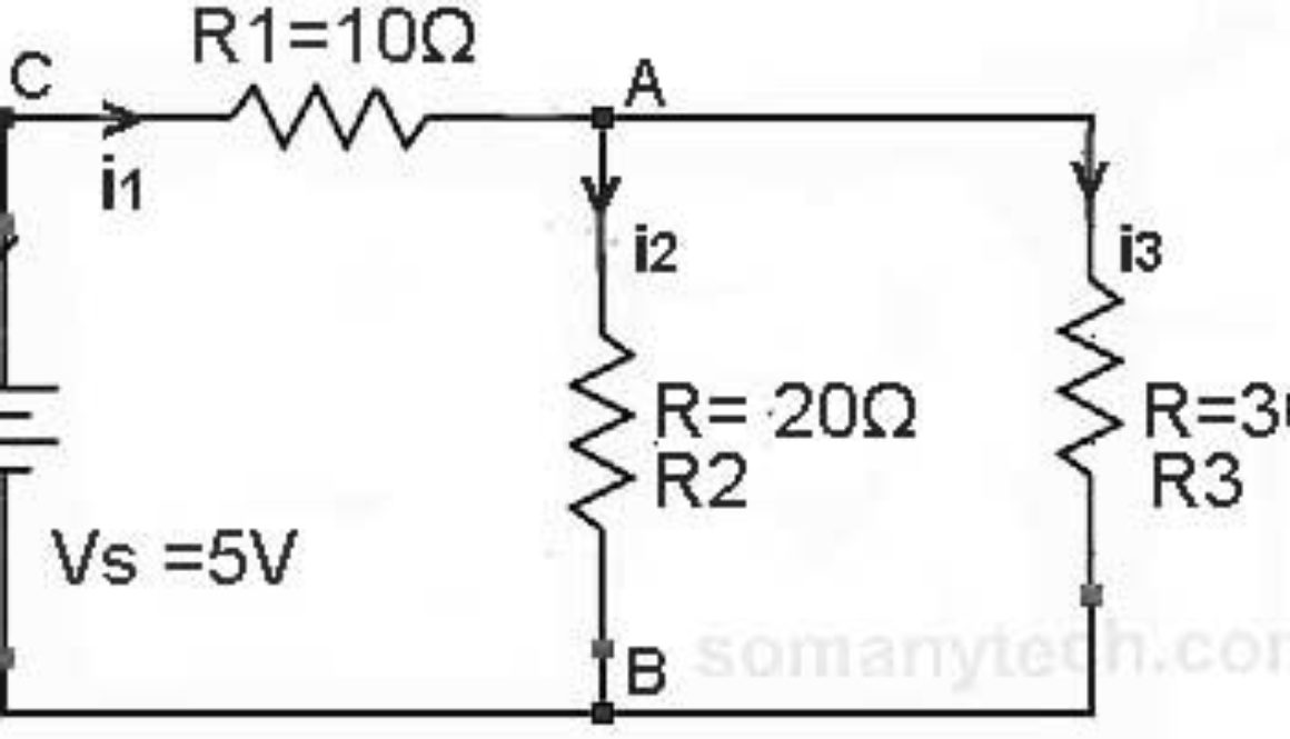
There is one resistor in series and two resistors with a power supply as shown in this circuit.
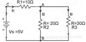
In this circuit, we need to calculate the current ‘I’ through each component.
- i1 = I (total) = Is = V(supply) / R(equivalent)
Here, R(equivalent) = R1 + Rp,
Also, 1 / Rp = 1 / R2 + 1 / R3∴ Rp = 12Ω & R(equivalent) = 22Ω - i2 = i1 * (R3/(R2+R3))
i3 = i1 * (R2/(R2+R3))
- The Voltage drop across R1 will be Vr1 = R1 * i1
A voltage drop across R2 will be Vr2 = R2 * i2
Voltage drop across R3 will be Vr3 = R2 * i3
Putting values we get,
Now, i1 = V(supply) / R(equivalent) = 5 /22 = 0.227 amps
∴ i1 = 0.227 A
Voltage drop across 10 ohm -> Vr1 = 10 * i1 = 10 × 0.227 volts
∴ Vr1 = 2.27 volts
Now, i2 = i1 * (R3/(R1+R2))
∴ i2 = 0.1362 A
Voltage drop across 20 ohm -> Vr2 = 20 * i2 = 20 × 0.1362 volts
∴ Vr2 = 2.724 volts
Now, i3 = i1 * (R2/(R1+R2))
∴ i3 =0.09 A
Voltage drop across 30 ohm -> Vr2 = 30 * i2 = 30 × 0.09 volts
∴ Vr3 = 2.7 volts
Method 2:
- Find i1 = V(supply) / R(equivalent) = 0.227 A
Then,Voltage drop across R1 will be Vr1 = R1 * i1 = 10 × 0.227 = 2.27 volts
∴ Equivalent voltage at point ‘A’ will be equals to Veq = Va = Vs – Vr1
∴ Va = 5 – 2.27 = 2.73 volts
Therefore, we get equal potential value across R2 & R3. - Thus, Va = Vr2 = Vr3 = 2.73 volts
Method 3:
In this method, we use a digital multi-meter or you can say a voltmeter. All you need is to set the multi-meter to voltage mode.
Now using its 2 probes check the voltage across the required resistor by connecting probes across it. (in fig. voltmeter reading is for indications only)
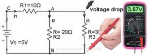
Voila !! You got it.
This is the easiest way to find a voltage drop across resistor in any circuit.

