Wiring a 4 Way Switch -Simple Wiring Diagram & Guide
Wiring a 4-way switch could be more complex as compared to a standard single-pole switch or a 3-way switch. It requires specific wiring connections and involves additional electrical connections other than live and neutral in the circuit. It is recommended to refer to the 4 way switch wiring diagrams when installing or wiring a 4-way switch to ensure safety and avoid short circuit over the wrong connections.
What is 4 way switches? Why it is used?
A 4-way switch is a type of electrical switch that is commonly used in residential and commercial buildings to control the lighting in a circuit from multiple locations. The 4 way switch wiring provides the means to turn on and off a light fixture independently, from up to four different switch locations. A long stare case or a large lobby can be an example for this kind of arrangement.
Here is the basic application diagram for simple understanding. This diagram showing the area of application of single pole switch, 3 way switch and a 4 way switch. Also remember some of the basic concepts along with the nomenclature and symbol for easy error free wiring. The different color is assigned to the screw for identifying the Common, Line and Ground.
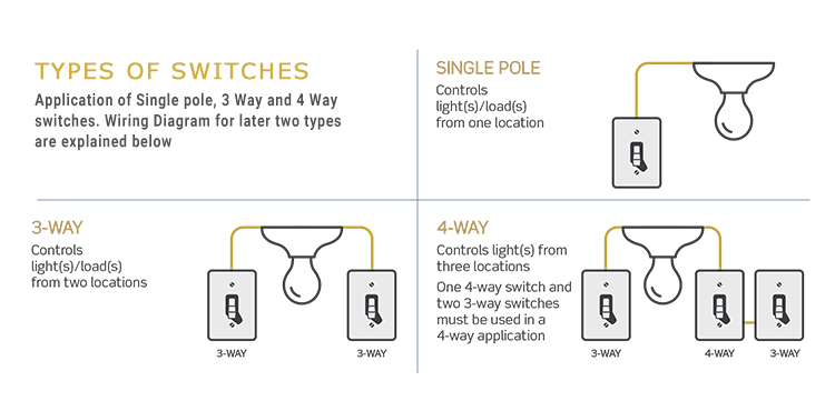
Also, note that wiring can be different for switches from different manufacturer company, so always check notation/ nomenclature discussed below. There are different variants available that have same functionality but with different position of input-output connection screws, or we can say different arrangements. And this can be tricky sometime for the electrician to connect or troubleshoot, that what we have covered below, so keep reading.
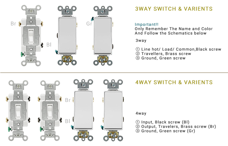
A 4 way switch can not be used as a standalone, it is used in combination with some 3-way switches.
In a typical setup, you have two 3-way switches at either end of the circuit, and one or more 4-way switches in the middle. The 4-way switch acts as a connector between the 3-way switches, allowing the circuit to be controlled from multiple points.
How to wire a 4 way switch?
Below is the most commonly used modular type, (one way to wire a 4-way switch, two 3-way switch and one 4-way switch is used to control a load (LED bulb) from 3 different location) wiring diagram for modular and decora switches. (Output/ traveler pins on vertical axis)
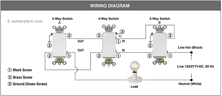
Wiring a 4 Way Switch in 3 Simple Steps:
- From two terminal of the (Bulb) Load, one terminal is connected to the Common /Black terminal of the 3 way switch ‘A’ , while the other end is connected to Neutral (White wire) to the mains supply. (120V AC, 60Hz)
- Traveler terminal from ‘A’ are connected to the Output/ Brass terminal of a 4-Way switch.
- Traveler terminal from ‘B’ are connected to Input/ Black terminal of a 4-Way switch.
- Common/ Black terminal from ‘B’ is connected to the Line Hot/ Live (Black wire) to the supply.
The above steps to be applicable for all types of 4 way control wiring and all types of switch if you know how to identify the Line/ Live, Neutral, Common, Traveler terminals. That too are generally mentioned on the switch or in the technical documents comes along with the switches.
Below is the another way to wire a 4-way switch having Output or Traveler pins on diagonal axis. Two 3-way switches and one 4-way switch is required to implement the circuit (LED bulb) from 3 different location)
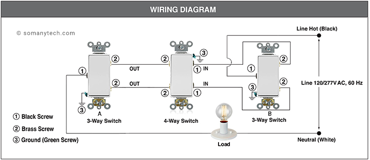
Important tips and tricks to remember while wiring:
- (T) Travelers are INPUT’s/ OUTPUT’s for whatever reason in case of a 4-way switch, this is to be cleared up for your strange brain.
- Don’t forget to connect the Green screw to the Ground/ Earth of the supply line.
- There are no standards for the colors of wires on 3-way and 4-way switch travelers. The colors could vary depending on whether it is an NM cable or conduit.
- With NM cable, the wire colors for travelers will be black and red using 3-wire cable. With conduit, the wire colors for travelers could be any color.
- For your reminder, every switch vendor sometimes have their own way of arranging the terminals, so the switches shown here may not match what you have bought are. Therefore, it is recommended to observe and locate the terminal accordingly.
Below (in this wiring diagram, one 4-way switch and two 3-way toggle switch is used to control a load (LED bulb) from 3 different location) wiring diagram for older traditional toggle switches.
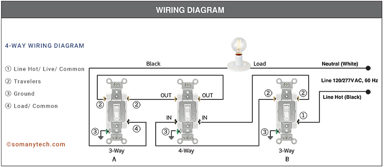
Wiring a 4 Way Traditional Switch Toggle type :
- Step one is to connect one of the terminal from Bulb to the ④/ Common of 3-way switch ‘A’, and another terminal to Neutral (White wire) of the mains supply.
- Now connect ②/ Brass traveler from 3-way switch ‘A’ to the Output/ Brass of the 4-way switch. Similarly, connect ②/ Brass traveler from 3-way switch ‘B’ to the Input/ Black of the 4-way switch.
- At the end, connect the ①/ Black terminal from 3-way switch ‘B’ to the Line Hot/ Live (Black wire) of the mains supply.
(link to download page, file at the bottom of the page)
Safety Precautions:
- To avoid fire, or fatal shock; turn off power at a circuit breaker or fuse and must ‘Ensure’ that power is off before wiring!
- Installed or used in accordance with local electrical codes and regulations.
- To clean, use a damp cloth without any soap or detergent. Do NOT use disinfecting products, including sprays or other types of atomized cleaning agents.


