Ola Electric has unveiled its indigenous made 4680 battery cell, named the “Bharat” cell, marking a significant leap in India’s electric vehicle (EV) technology. Developed entirely in-house, the Bharat cell boasts cutting-edge advancements in battery technology and aligns with India’s push for self-reliance in the EV sector.
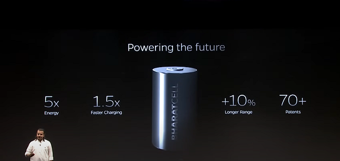
Ola’s new cells are bigger, provide about five times as much energy, and have faster charging times compared to the previous 2170 cells used in Ola’s electric scooters. The Bharat 4680 is developed as a new cell with a much bigger form factor and proprietary technology.
What is the Bharat 4680 battery by Ola?
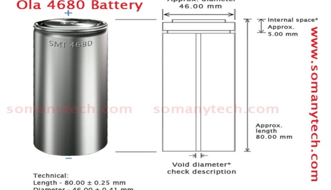
The Bharat 4680 battery is a Li-ion battery, named after its 46mm × 80mm cylindrical size (diameter × height). When compared to 2170 size cells, the height and diameter both are larger. It would replace the 2170 battery, which is currently being used in Ola’s electric vehicles.
The Bharat 4680 battery type would be popular in rechargeable and high-current draining devices considering its higher degree of capabilities like charge cycle and higher energy density.
Ola’s Bharat 4680 battery specification:
Properties
Specifications
Remark
Component type
Battery/ Cell
Power supply
Battery type
Li-ion
Technology
Model No
4680
Bharat 4680 battery
Size/ dimension
46 ✖ 80 mm
Standard (dd ✖ hh)
Voltage
3.7 volt
Nominal (std).
Capacity
25- 26Ah
Per cell (estimated max)
Operating voltage
2.5- 4.2 volt
Range (std.)
Weight
~355 gms
(estimated)
Charge density
(Energy per cell)
96-99 Wh
Energy (at 3.7V estimated)
Charge discharge cycle
~1500
(1000 to 2000) in number (depends on nature of charging)
Charging voltage
4.2v- 5v
5 volt max per cell
The Bharat 4680 cell, named after its 46mm × 80mm cylindrical size (diameter × height), represents a substantial improvement over the existing 2170 cells currently used in Ola’s electric scooters. Key features include:
Energy Density: The Bharat cell offers five times more energy density than the 2170 cells, leading to significantly improved performance and range for electric vehicles.
Charging Efficiency: Enhanced charging capabilities ensure faster charging times up to 1.5X, adding to a better user experience, as the current battery needs to be charged for about 7-8 Hrs to get it 100%.
Patent Portfolio: According to sources, Ola Electric has secured over 70+ patents related to this upcoming Bharat cell, which indicates the innovative and proprietary nature of this technology.
With the confirmation of the new cell being 4680, the name of this new cell is given: the Bharat 4680 battery cell. This post covered all known and possible Bharat 4680 battery specifications.
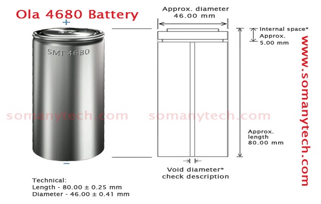
Ola 4680 battery size / dimension:
The 4680 battery length is 80mm.
The diameter of the 4680 battery is 46mm.
To be more precise, it has an approximate length of 80mm and an approximate diameter is 46mm.
Thus, you could find specifications written as (say) 46 ± 0.41mm ✖ 80 ± 0.25mm on the datasheet and features of the li-ion cell.
Advantage of 4680 over previous 21700 batteries:
Due to the increase in length and diameter, the overall volume of the cell has increased, thus, with this development, it is claimed that there will be a 5x increase in capacity and a 6x increase in power. Supports one and a half times faster charging rate as compared to the previous 18650 battery. Check here What is 21700 battery?
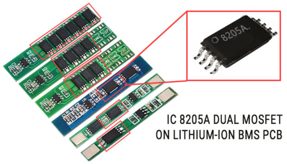
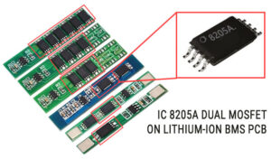
Here is the detailed information on the features, applications, uses, and specifications of this popular and most commonly found dual Mosfet 8205A IC with datasheet. If you are looking for a high current transistor to use in battery protection, load switching, or power management PCB circuit, this Dual MOSFET is designed in a way to meet your needs in lithium battery protection circuits. Also provided 8205A Datasheet.
What is the 8205A IC on the lithium-ion battery protection PCB circuit?
8205A IC on the lithium-ion battery protection PCB circuit is dual Mosfet 8205a IC, its function is to control or halt the current through the battery in the situation or as signaled by the controller IC (e.g. DW-0, TP4056, etc.) in case of short circuit, over-current, over-voltage, or over-temperature or over discharge as specified by the controller IC.
8205A Datasheet
Below is the 8205a datasheet from HSMC for reference, download this datasheet at the bottom of the page. Please note that other than pinout/ pin number some specifications may vary slightly from manufacturer to manufacturer. But they can be used as an alternative to each other.
8205A Pinout:
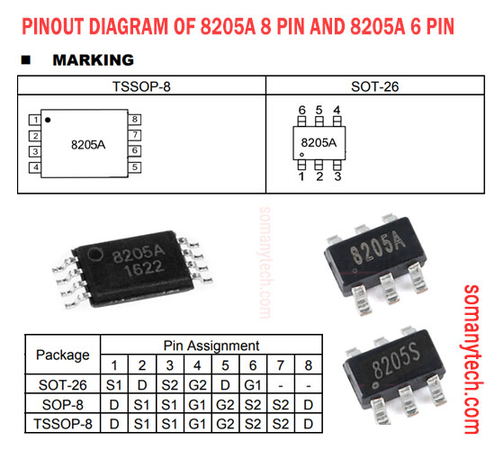
To understand the connections and functionality, let’s explore the pinout of the 8205A showing with the image that includes all 6 pin IC (SOT-26 package) and 8 pin IC (SOP-8 & TSSOP-8 package):
Apart from the pinout diagram, the function and application circuit diagram will be the same for both 6 pin SOT-26 and 8 pin SOP-8.
The pin assignment for the 8205A 6 pin IC (SO-26 package) is described as follows:
The main function of 8205A is to act as a control switch that regulates the flow of current in a circuit.
The 8205A MOSFET found in various circuits, including:
Lithium-ion Battery Protection circuit & Battery Management System: This MOSFET is commonly used in battery protection circuits and management circuits, which is then used for the safe and efficient operation of lithium-ion batteries.
Load Switching Circuit: Its ability to handle high power, current and fast switching makes it suitable for load switching applications in electronic devices.
8205A IC equivalent are 8205S, DMD9926, DMG6968 etc
The 8205A and 8205S are both dual N-channel power MOSFETs, but they have some differences in their electrical characteristics and specifications.
The 8205A has a maximum drain-source voltage of 30V, while the 8205S has a maximum of 20V. The 8205A also has a higher maximum continuous drain current of 8A, compared to the 8205S, which has a maximum of 5A. (also subjected to the different manufacturer)
In terms of their electrical characteristics, the 8205A has a lower drain-source on-state resistance (RDS(on)) than the 8205S. Before reaching any conclusion, you must refer to the datasheet corresponding to the manufacturer or component provider.
At last, the choice between the 8205A and 8205S would depend on the specific requirements of the application, such as the maximum voltage and current needed, as well as the desired RDS(on) value. So, it can be said that 8205s can be replaced by 8205A.
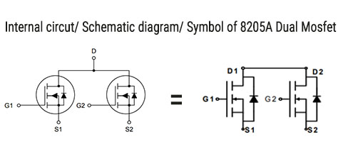
8205A IC circuit diagram schematic:
Image showing internal circuit diagram of 8205A IC, the Drain terminals are shorted internally and available as Drain 1 Drain2 = D
Utilize to the fullest the Android phone with the Best Scientific Calculator App, this app is very useful for Students, Engineers, or anyone requiring to calculate large complex scientific calculations which are more time consuming and not necessary to do manually.
This powerful tool combines advanced mathematical functions with a user-friendly interface, making it the perfect accessory tool for anyone in need of precise calculations for engineering mathematics. With an array of scientific functions at your fingertips, these app allows you to effortlessly perform complex calculations, including trigonometry, logarithms, exponential, and much more. Say goodbye to manual calculations and let these android app handle complicated equations with speed and accuracy.
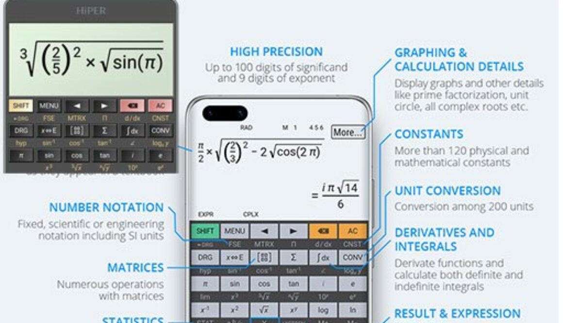
The top calculators in this list are very useful as they are an all-rounder in all sorts of calculations. Specially HiPER scientific calculator is self-contained for most of your engineering calculations.
HiEdu Scientific Calculator: He-570 is a simply powerful best scientific calculator app that includes standard, scientific, and programmed modes, as well as unit converter, number system conversion, and the equations solver. It’s the all-rounder tool to work with, from billing, measurement conversion in a project, or the academics assignments. And it is a very useful tool for engineers helps to complete complex math, algebra, or geometry problems.
Key Features:
Natural display, scientific Calculations, standard Calculations, mathematical formulas, Physics formulas, Graphing Calc. Inbuilt Programmers can convert numbers between different number bases (2/8/10/16). The display shows numbers in binary, hexadecimal, octal, and decimal, the input can be in binary, hexadecimal, octal, or decimal.
Almost all unit Converters required in day to day life are included like Currency (US dollar, UK pound, IN rupee, JP yen). temperature (Celsius, Fahrenheit, Kelvin), Length (kilometers, miles, meters, yards, feet). Mass (kilograms, pounds, ounces, ton, etc). Speed (km/h, mph, etc). Area (sq. km, sq. miles, hectare, acre, etc). Pressure (kilopascal, bar, PSI, etc). Power (watt, Kw, Hp, etc). Energy in (Joule, Kcalorie, BT). Time (in years, days, hours, seconds). Memory in digital Storage (bit, byte, Kb, Mb, Gb)
HiPER Scientific Calculator
By HiPER Labs
Description:
HiPER Scientific Calculator is a popular android app calculator with more than 15 million downloads and a huge number of five-star ratings.
This calculator has the ability to calculate up to 100 digits of significand and 9 digits exponent. It can detect repeating decimals and numbers and converts them to fractions or decimal equivalent. You can enter equations and expressions in a natural way as you type. The result is displayed as a number or simplified eq.
Features:
You can change the Themes and layout according to your comfort. It has 10 memory slots and 90 scientific constants. As a calculator, it can do basic arithmetic operations including percentage, modulus, and negation.
Fractions in the expression mode can be entered as a numerator and/ or denominator. All the scientific operations required in engineering are supported in HiPER Scientific Calculator.
Scientific Calculator
(formerly known as PowerCalc app)
Developed by Appsbuyout Dev
Description:
Easy and user-friendly to use with realistic appearance. Scientific Calculator is a powerful best Android scientific calculator with a real physical look. It is one of the few Android calculators apps that can solve complex number equations.
Features:
Real equation view editor with brackets and operator priority function, normal or polar complex mode. It can solve equations and save results in history. 7 memories for easy value recalls. You can access Constant Table in memory containing Large universal/ physical/ mathematical/ chemical constants. Degrees, radians, and grads mode for trigonometric operations.
It can do mathematical operations that include equations. Best suited for engineering or graphical calculations.
Pro feature:
It has some paid features that include multi-line equation editor, equation syntax highlighting, actual bracket highlighting, trigonometric functions with complex numbers.
Free Advanced calculator 991 es plus & 991 ex plus
By Nhi Thien Studio Education
Description:
Calculator 991 ES/ 570 ES/ 991 EX is one of the best classroom calculators for Android. The best scientific calculator app 991ES and 570ES of choice for engineers & high school buddies. Natural screen display, powerful and fast functions in it make it highly recommended.
Most of the people download this app thinking of its UI/UX but wait a minute, it does not look like the original 991es physical hard calculator. It might be disappointing to the person who is downloading it thinking of its appearance other than its original UI user interface. This calculator in its equipment form is mostly used by engineering and doctorate students for long and complicated calculations.
Feature :
All necessary features are included from memory to recall function and from number system conversion to complex numbers, everything you want and you need.
Download Calculator 991ES/ 570ES.
Direct APK download
RealCalc Scientific Calculator
By Quartic Software
Description:
RealCalc Scientific Calculator app has over 20 million downloads on the Google play store and 189k+ 5* reviews. It is one of the most popular scientific calculators for Android. RealCalc has somewhat like an artificial look not natural but operates exactly like a real calculator. It has all the standard scientific functions with history, 10 memories, unit converter, and constants table. You can choose from a number of display styles and formats.
It also supports binary, octal, and hexadecimal conversion and operations. RealCalc is easy to use comes with the help section included.
Features:
User-customizable unit conversions and custom constants feature so that you can save each.
All engineering and scientific calculations along with Landscape mode is supported.
APK download
Scientific Calculator free
By RealMax LK
Description:
This is a simple user-friendly scientific calculator app for all your mathematical and engineering calculation tasks.
It has over 1M+ downloads on play store, Download Scientific Calculator 995 (sc-995) for android, it has 76 different functions, binary/octal/hexadecimal conversion, and all mathematical operations. Its memory supports up to 10 variables, Angular measurement in Degrees, Radian, Minute and also able to plots graphs. All Basic Operations, trigonometric and hyperbolic operations, logarithmic operations-complex number-Matrix Operations, 10 variables, HEX, DEC, OCT, BIN conversion, fractions, Degree, Minute, Seconds calculations, Radian, Solving Linear and quadratic equations.
Scientific Calculator Advanced (Free)
By Scientific SoftwareTools
Description:
An essential tool for engineering students. Turn your phone into the best scientific calculator app you can use it 0n android.
Basic, advanced, and graphing modes let you use just what you need when you need it. It’s fast, easy to use, and looks like the real thing.
Best of all, you’ll never lose your scientific calculator when you need it – Scientific Calculator Free goes where you go but Ads in tha apps may bother you.
Feature:
Full color output graphs and display, supports landscape and portrait mode,trigonometry/ log/ exponents/ fraction / complex numbers, Linear/ polynomial equations. Binary, decimal, hexadecimal operations and conversions.
Panecal Scientific Calculator
By Appsys
Description:
It has over 5M+ Downloads, Panecal scientific calculator is feed with lots of mathematical formulas to check your formulas, which enables you to prevent typo. Inbuilt memory enables the function to edit past calculations. This app is preferred by many people for their educational calculation utility. A cursor is displayed on the screen to quickly move to the location on the screen you want quickly to edit.
Panecal allows swipe to scroll through formulas, as well as copy-paste using long tapping, which makes it a user-friendly interface. Also, the display shows the cursor, and you can tap or press the arrow keys to quickly navigate to where you want to edit.
Features:
Vibration response, easy editing with a cursor also copy-paste text, previous question history and answers history in tabular form.
Any base number operation and conversion upto 32bits. Arithmetic, trigonometric, logarithmic, degrees-minutes-seconds calculations. Deg, Rad, Grad, decimal point character. Portrait and landscape screen settings.
The TP5100 is one of the most widely used battery charging controller IC/ BMS. It is a simple and cost-effective IC that is designed for large current portable electronic devices. One of the main advantages of the TP5100 IC is its compact and simple external circuit, and requires only a few basic additional components to function.
It has several safety features to protect the battery and the charger from being damaged. It can be easily purchased from online retailers or electronics suppliers as a module.
You could implement an 18650 battery charger circuit using TP5100 in two ways, one directly with the TP5100 module available in the market and the other with the TP5100 charger IC. Both are discussed and explained in detail below:
TP5100 is dual mode charging management chip, means it can charge 18650 battery or any 3.7v battery in two ways, one with the dual as well as single cell charging mode with 8.4V/ 4.2 volts.
Main features of TP5100:
Dual 8.4v / 4.2v operation for Li- ion cells.
Programmable charge current from 100mA -2000mA.
Wide operating voltage, from 5V to 18V, with SET/ Mode selection.
Charge Indicator: Blue LED – battery full/ standby; Red LED – charging indicator.
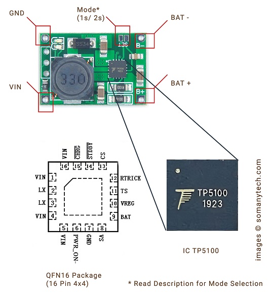
Pin
Remark
1,4,5,16 - VIN
Input supply voltage
2,3 - LX
Power drain MOS-FET connection
6 - PWR_ON¯
Enable/Disable IC (Float)
7 - GND
Ground return
8 - VS
Positive feedback for output current detection
9 - BAT+
Battery positive
10 - VREG
Internal power supply
11 - TS
Temperature sense of battery (refer to datasheet)
12- RTRICK
Trickle pre-charge current set
13 - CS
Chip select input (Float)
14 - STANDBY¯
Charging indicator
15 - CHRG¯
Full charge indicator
Specification:
Switching frequency 400Khz, usable inductance 22uH/ 33uH and more.
Size: 25 * 17 * 5mm ultra-small size.
Input operating voltage: 5-18V DC power supply.
PWR_ON Power battery for switching control.
Absolute maximum voltage: 20V
Operating temperature range: -40 ° to 85 °
BAT Short-Circuit Duration: Continuous.
Chip temperature protection, over-current protection, under-voltage protection.
Battery temperature protection, reverse battery shutdown, short circuit protection.
Steady pre-charge current programmable to 10% -100% of charging current.
TP5100 Application:
Portable equipment, lithium battery various chargers, Smartphone, Audio Bluetooth players, Industrial commercial power supply maintenance.
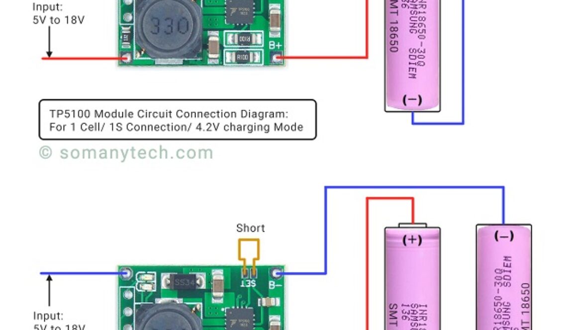
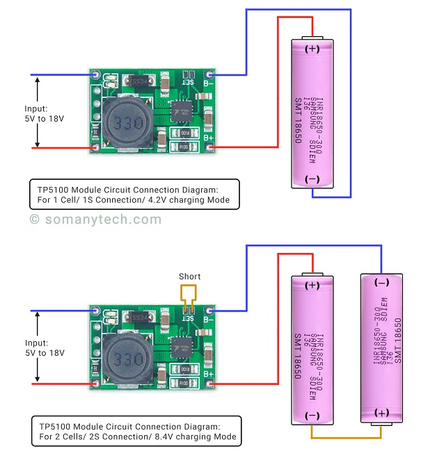
Below is the simple TP5100 Charging module schematic diagram for single cell li-ion and dual cell. The main IC of the module is the TP5100 chip, which is from manufacturer ‘Top Power ASIC’. It has become quite popular for charging 3.7V li ion batteries as it has all the required battery protection feature like over-charge, short circuit, under voltage and over-temperature protection.
For single battery circuit it uses the 4.2V charging voltage by default, but for dual cells in tp5100 charging module needs to connect ‘SET’ on the module board for 8.4V operation.
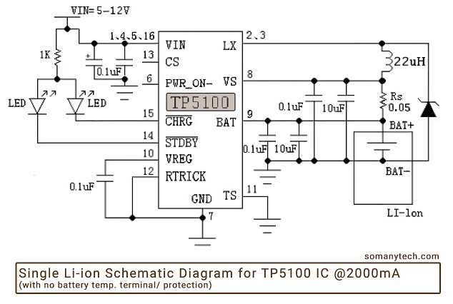
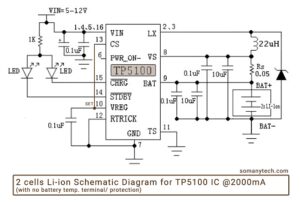
Below is the simple circuit diagram for the Li-ion battery charger schematic according to the datasheet of TP5100 with temperature sense disabled.
The Red LED glows when the battery is charging or module is in standby mode, and the Blue LED glows when the battery is fully charged. These indicators are connected to pin number 14 and pin number 15 respectively.
So here’s the TP5100 1s connection for single 3.7V li-ion battery.
The TP5100 module 2s connection manual for dual 3.7V li-ion batteries in series and 8.4 V is selected with ‘SET’ (short circuit).
Components required:
IC TP5100, 2x LED indicator, 3x Cap= 10.1uF (0.1uF || 10uF), 1x Cap= 0.1uF, Ind=22uH or 33uH, 1x Resistor= 1KΩ, Rs= 0.05Ω (2 x R100 SMD resistor 0.1Ω || 0.1Ω), 3.7V Lithium cells, micro USB/ USB C female connector, customized PCB.
Description:
This circuit can be used only for rechargeable battery charging purposes. Here, Rs is chosen to be 0.05Ω for 2000mA of output current. If we talk about TP 5100, it is a switching dc-dc buck regulator. Thus, in Mode 1 (1S), it is required to supply ~5V, and in Mode 2 (2S), it should be ~12V for intended operations.
Mode 1 (Default): You need to just connect 1 Lithium battery across BAT+, BAT- (GND); that’s all, the module will take care of charging process.
Mode 2 (SET): You need to connect 2 Lithium battery in series across BAT+, BAT- (GND); and Connect CS/ Pin 13 with VREG Pin 10 (for module pin “SET” to be connected) for correct charging process.
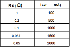
The charging current (IBAT) of the li-ion cell can be set manually by choosing the value of Rs. In all the modes during charging, the charging current could be determined as follows. The Rs(Ω) vs Ibat(mA) can be determined using the following table :
Note: If you have two 18650 lithium batteries, then by connecting them in series (short-circuit “SET” connections), each battery will charge at 1000mA of current. If you connect one Li-ion battery then it will charge it at the rate up to 2000mA, thus it will charge faster compared to TP4056 module to fully charge a battery.
There are several Charge Controller ICs available in the market, but here discussed popular ones are TP5100, and TP4056. It will help you choose the right one for your application.
TP5100 is an upgraded version of TP5000 with a maximum charging current of 2A. TP4056 is another charge controller IC with a maximum charging current of 1A.
IC TP5100
IC TP4056
Max. charging current
2000mA
1000mA
Li-ion cell
1s, 2s (single & dual cells)
1s (single cell)
Operating voltage/ Input
5V to 18V
5V to 8V
Charge voltage
4.2V, 8.4V
4.2V
Charging voltage control accuracy
>1%
~1.5%
Initial current
no soft-start
soft-start limits inrush current
In conclusion, TP5100 is a more advanced and flexible charge controller IC than TP4056. However, if you are looking for a simple and low-cost charge controller IC, TP4056 may be the right choice for you. The TP5100 is a good option for charging dual-cell lithium-ion or lithium-polymer batteries in power efficient applications.
Before choosing a charge controller IC, it is important to consider the requirements of your application, such as the charging current and charging time.
FAQ:
How many batteries can charge in TP5100?
You can charge one, two or more lithium battery cells with TP5100, but note that it has a max 2000mA of charging current. So, when charging multiple cells, you have to connect them in parallel. Also, the charging current will be divided among them, which will make charging slower. It is recommended to utilize two to four cells at a time with this module.
What is the output current of TP5100?
The maximum output current of TP5100 is 2000mA. It can be programmed to provide charging current from 100mA to 2000mA by changing the value of Rs.
What is the use of TP5100 module?
The TP5100 Module is used to charge either single or double 3.7 lithium-ion cell/ battery at 2Amp of current.
What is the input voltage of TP5100?
The input voltage of TP5100 is minimum 5V for single cell and 12- 18V for dual 3.7 lithium-ion cell.
When using a Leviton 4 way switch wiring diagram and setup, you can control the single light fixture from 3 different locations, while two locations can be operated by using a 3 way switch wiring diagram and setup. In this post you’re going to learn the wiring process for Leviton 4-way switch and 3 way switch setup in the traditional toggle switch configuration or with the modular/ decora. However, the wiring could be a little bit complex but very implementable by keeping proper terminology in consider. Let’s break down the process step by step for clarity.
Assumptions:
You have a single light fixture (bulb) that you want to control from three locations using traditional toggle switches.
You’re using standard electrical wiring, where Black wires are live/hot, White wires are neutral, and bare or green wires are ground.
Materials you’ll need:
Three 3-way toggle switches (labeled A, B)
One 4-way toggle switch (middle)
Electrical connecting wires (black, white, and green)
Wire nuts or other suitable connectors, screwdrivers, wire stripper/cutter.
Leviton 4 way switch wiring diagram:
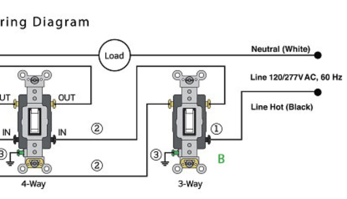
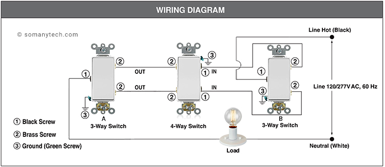
In the below wiring diagram, one 4-way switch and two 3-way switch is used to control a load (LED bulb) from 3 different location) wiring diagram for older traditional toggle switches.
Leviton 4 Way Switch wiring diagram:
• Begin by attaching one terminal of the Light Bulb to the Common (here marked as “④”) terminal of the 3-way switch labeled ‘A’.
The other terminal of the Bulb should be connected to the Neutral wire (usually White) from the main power supply.• Now, proceed to link the Brass traveler wire labeled “②” from 3-way switch ‘A’ to the Output/Brass terminal of the 4-way switch (middle one).
Similarly, connect the Brass traveler wire “②” from 3-way switch ‘B’ to the Input/Black terminal of the 4-way switch.
• Finally, make a connection between the Black terminal labeled “①” of 3-way switch ‘B’ and the Line Hot/Live wire (typically Black) of the main power supply.
Connection with Leviton 3 way switch wiring diagram is way simpler than that of 4 way switch as we need to wire only two switches, discussed below in detail.
Assumptions:
• You have a single light fixture(LED bulb) that you want to control from 2 different locations using traditional toggle switches.
• You’re using standard electrical wiring, where Black wires are live/hot, White wires are neutral, and bare or green wires are ground.
Materials you’ll need:
• Two 3-way toggle switches.
• Electrical wires (black, white, and green)
• Wire nuts or other suitable connectors, screwdrivers, wire stripper/cutter.
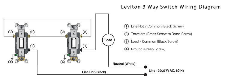
3 way switch wiring Leviton:
• First, connect any one terminal of Load/ bulb to the Common (Black Screw) of the switch ‘B’. Then connect the 2nd terminal of Load to the Neutral/ (White wire) of the mains supply.
• Now, connect Common (Black screw) from switch ‘A’ to the Line Hot of the mains supply.
• Remaining are the Travelers connections, connect both the Travelers from switch ‘A’ to switch ‘B’. (Brass screw from switch ‘A’ to Brass screw of switch ‘B’)
• Don’t forget to connect the ground screws to the ground cable, commonly colored green.
Download 4 way switch wiring diagram PDF and 3 way switch wiring diagram PDF below.
Note: Leviton here is the trademark of the respective company, this website doesn’t own or claim any kind of copyright regarding the design of the switch.
Wiring a 4-way switch could be more complex as compared to a standard single-pole switch or a 3-way switch. It requires specific wiring connections and involves additional electrical connections other than live and neutral in the circuit. It is recommended to refer to the 4 way switch wiring diagrams when installing or wiring a 4-way switch to ensure safety and avoid short circuit over the wrong connections.
What is 4 way switches? Why it is used?
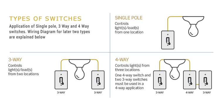
A 4-way switch is a type of electrical switch that is commonly used in residential and commercial buildings to control the lighting in a circuit from multiple locations. The 4 way switch wiring provides the means to turn on and off a light fixture independently, from up to four different switch locations. A long stare case or a large lobby can be an example for this kind of arrangement.
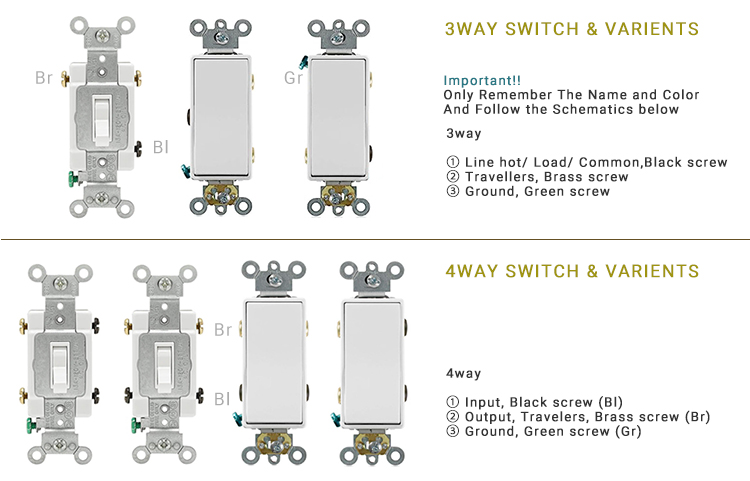
Here is the basic application diagram for simple understanding. This diagram showing the area of application of single pole switch, 3 way switch and a 4 way switch. Also remember some of the basic concepts along with the nomenclature and symbol for easy error free wiring. The different color is assigned to the screw for identifying the Common, Line and Ground.
Also, note that wiring can be different for switches from different manufacturer company, so always check notation/ nomenclature discussed below. There are different variants available that have same functionality but with different position of input-output connection screws, or we can say different arrangements. And this can be tricky sometime for the electrician to connect or troubleshoot, that what we have covered below, so keep reading.
A 4 way switch can not be used as a standalone, it is used in combination with some 3-way switches.
In a typical setup, you have two 3-way switches at either end of the circuit, and one or more 4-way switches in the middle. The 4-way switch acts as a connector between the 3-way switches, allowing the circuit to be controlled from multiple points.
How to wire a 4 way switch?
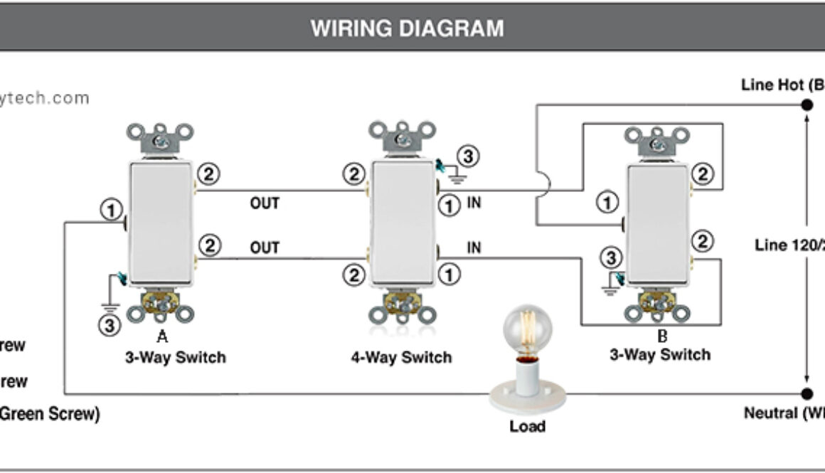
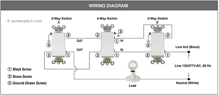
Below is the most commonly used modular type, (one way to wire a 4-way switch, two 3-way switch and one 4-way switch is used to control a load (LED bulb) from 3 different location) wiring diagram for modular and decora switches. (Output/ traveler pins on vertical axis)
Wiring a 4 Way Switch in 3 Simple Steps:
From two terminal of the (Bulb) Load, one terminal is connected to the Common /Black terminal of the 3 way switch ‘A’ , while the other end is connected to Neutral (White wire) to the mains supply. (120V AC, 60Hz)
Traveler terminal from ‘A’ are connected to the Output/ Brass terminal of a 4-Way switch.
Traveler terminal from ‘B’ are connected to Input/ Black terminal of a 4-Way switch.
Common/ Black terminal from ‘B’ is connected to the Line Hot/ Live (Black wire) to the supply.
The above steps to be applicable for all types of 4 way control wiring and all types of switch if you know how to identify the Line/ Live, Neutral, Common, Traveler terminals. That too are generally mentioned on the switch or in the technical documents comes along with the switches.
Below is the another way to wire a 4-way switch having Output or Traveler pins on diagonal axis. Two 3-way switches and one 4-way switch is required to implement the circuit (LED bulb) from 3 different location)
Important tips and tricks to remember while wiring:
(T) Travelers are INPUT’s/ OUTPUT’s for whatever reason in case of a 4-way switch, this is to be cleared up for your strange brain.
Don’t forget to connect the Green screw to the Ground/ Earth of the supply line.
There are no standards for the colors of wires on 3-way and 4-way switch travelers. The colors could vary depending on whether it is an NM cable or conduit.
With NM cable, the wire colors for travelers will be black and red using 3-wire cable. With conduit, the wire colors for travelers could be any color.
For your reminder, every switch vendor sometimes have their own way of arranging the terminals, so the switches shown here may not match what you have bought are. Therefore, it is recommended to observe and locate the terminal accordingly.
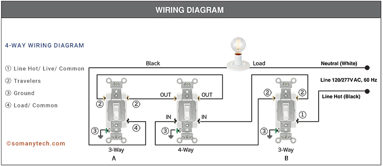
Below (in this wiring diagram, one 4-way switch and two 3-way toggle switch is used to control a load (LED bulb) from 3 different location) wiring diagram for older traditional toggle switches.
Wiring a 4 Way Traditional Switch Toggle type :
Step one is to connect one of the terminal from Bulb to the ④/ Common of 3-way switch ‘A’, and another terminal to Neutral (White wire) of the mains supply.
Now connect ②/ Brass traveler from 3-way switch ‘A’ to the Output/ Brass of the 4-way switch. Similarly, connect ②/ Brass traveler from 3-way switch ‘B’ to the Input/ Black of the 4-way switch.
At the end, connect the ①/ Black terminal from 3-way switch ‘B’ to the Line Hot/ Live (Black wire) of the mains supply.
(link to download page, file at the bottom of the page)
Safety Precautions:
To avoid fire, or fatal shock; turn off power at a circuit breaker or fuse and must ‘Ensure’ that power is off before wiring!
Installed or used in accordance with local electrical codes and regulations.
To clean, use a damp cloth without any soap or detergent. Do NOT use disinfecting products, including sprays or other types of atomized cleaning agents.
Logic Gate Simulator Download PC Free Full Version
For Windows
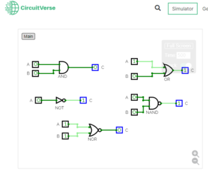
CircuitVerse Download:
Circuitverse is an Online Logic Gate Simulator application. CircuitVerse Simulator empowers you to capture complex circuit designs with precision through high-resolution image export, including SVG, facilitating impressive sharing and display capabilities… read more
Free Online version:
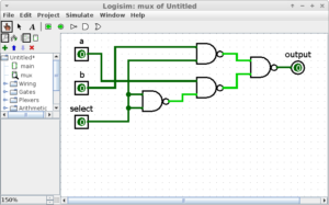
Logism Download:
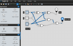
Logisim is one of the popular logic gate simulator for Windows PC. It allows you design and simulate logic circuits and also have the capability to views truth table, expression. Important concepts like Product of Sums POS and Sum of Products SOP simplifications. It also provides a variety of components to add to your logic circuit design, like multiplexer, demultiplexer, adder, subtractor, divider, and many more.
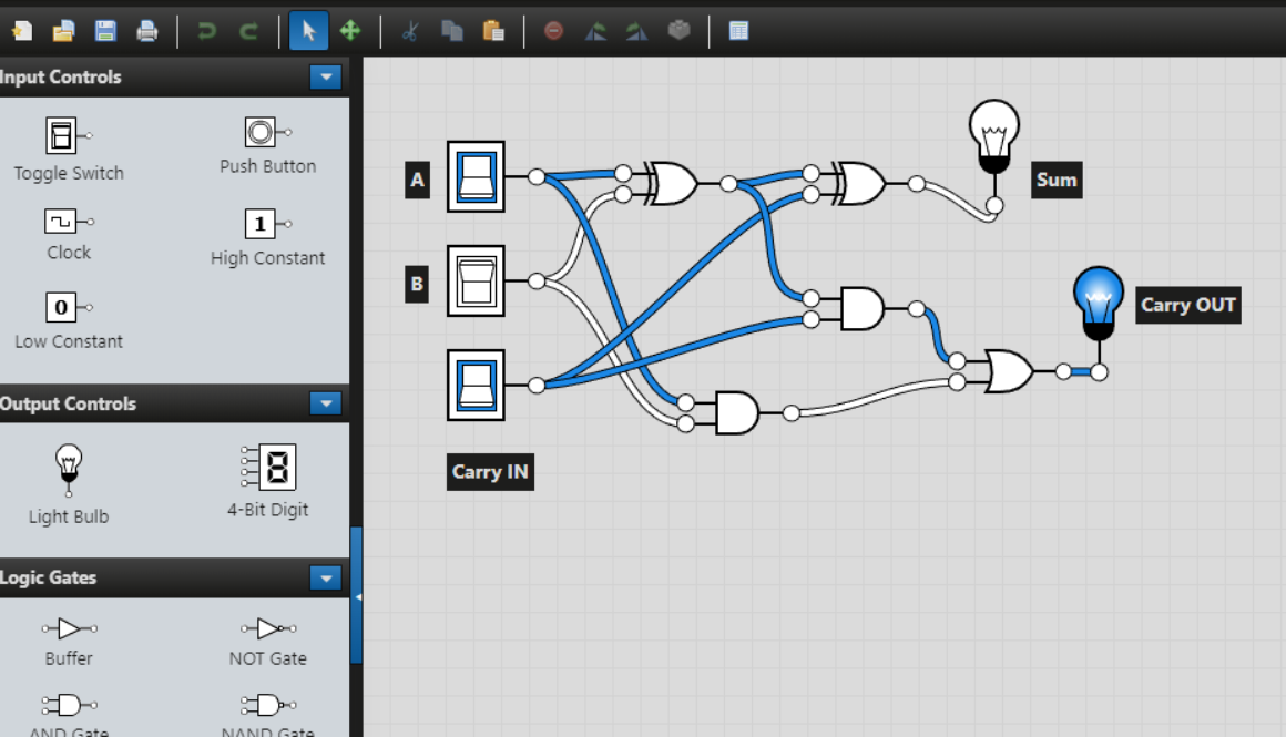
Logic.ly Download:
Free Version: https://logic.ly
Paid Version Download:
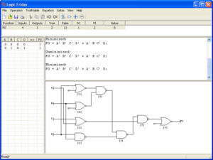
LogicFriday Download:
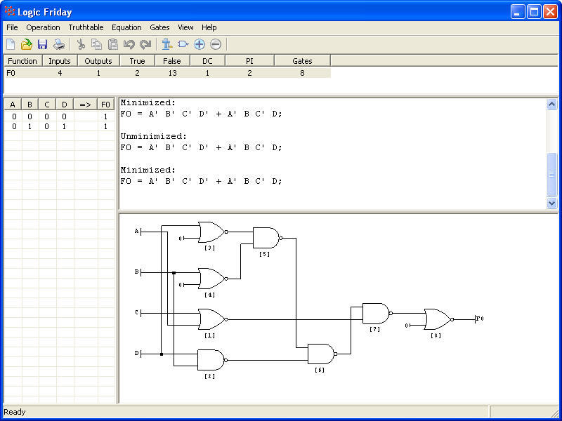
Logic Friday is an offline tool that simplifies the process of digital logic design and makes it enjoyable. With LogicFriday, you can visualize your logic functions in multiple windows, analyze truth tables, equations, and gate diagrams effortlessly…
You get basic gates NOT/Inverter, AND, OR; compound gates like NAND, NOR, XOR, XNOR, and input/output Signal indications. Features like (user/numeric input, user/numeric output, clock period in ms, comment, etc.) to draw a logical circuit. You need to drag and drop the components to the main window to create the desired logic gate design. You can also add multiple inputs to a gate, connect components using wire, rename components.
It shows real-time simulation of logic gates on input change. Also, you can use ‘Show Logical Analyzer’ button to view logic gate simulation in oscilloscope simulate view which is very exciting.
Logic Gate Simulator Download Free APK
Logic Gate Simulator App for Android
Smart Logic Simulator:
by Tomasz Czart [Wrapptec]
Smart Logic Simulator makes designing circuits easy by its friendly user interface. You can scale your projects rally quickly by using inbuilt custom IC feature, which allows you to pack advanced circuits into single reusable components and importing is also possible with this android app.
Logic Circuit Simulator Pro:
by Stefan Belinov
Create amazing logic circuits with all the essential logic elements. Use variety of elements to evolve, experiment and learn electronics. This simulator makes designing ‘Combinational Logic Circuit’ quick and easy by its intuitive interface and a lot of options to explore. This android application provides a lot of information for all the elements that can be used.
-Import, export and share circuits by ease.
-Embed circuits in each other.
-Many tutorials and use tips are here to help, if you struggle.
-Many elements which are used in electronics are available – lots of logic gates, programmable arrays, latches, flip-flops, generators, device sensors…
Logic Gate Simulator:
by rain continues
Logic Gate Simulator for Android, Digital Logic Circuit simulation and schematics. Build and simulate Digital circuits right on your Phone. Build logic circuits with logic gates and other components then simulate. As it is extremely simple and easy to use, it takes no time to learn how to use it, suitable for students and teachers who’s learning how digital logic circuit works.
EveryCircuit is a pack of custom-built simulation engine optimized for interactive mobile use, serious numerical methods, and realistic device models. Simplicity, innovation, and power, combined with mobility, make EveryCircuit a must-have companion for high school science and physics students, electrical engineering college students who are interested in Digital logic simulation.
The essential components of any digital circuits are the Logic Gates, which contributes to the essential logical building blocks required by electronic systems to operate.
In addition to helping engineers to implement their idea into designs, logic gate simulator software gives you the power to effortlessly design and simulate complex logic circuit diagrams, whether you’re an engineering student or an experienced engineer looking to deepen your understanding.
From vast features at your fingertips, the possibilities are boundless. Designing complex digital circuits becomes painful as you explore the extensive range of components, including multiplexers, de-multiplexers, adders, subtractors, dividers, multipliers, registers, counters, RAM, ROM, and much more. Create complex circuits and simulate them in real-time while being able to observe digital output as you modify accordingly.
In this article, we will be discussing the top best logic simulator software programs for both PC and your Android mobile phone:
Logic Simulator Online & Offline
And important thing is all the simulator software programs works into two steps: Design and Simulate. To simulate any type of digital circuit, you need to first design using the symbol provided on the toolbar or components area, then after completion of the design check for errors and press simulate button. Simulation will provide the final output of the given digital logic circuit.
CircuitVerse Simulator:
Circuitverse is an Online Logic Gate Simulator application. CircuitVerse Simulator empowers you to capture complex circuit designs with precision through high-resolution image export, including SVG, facilitating impressive sharing and display capabilities.
It is also able to simplify complex logic circuit projects effortlessly with ‘CircuitVerse’s Combinational Analysis’ feature. By inputting truth table data, this application automatically generates circuits also supports sub-circuit conversion, enabling an organized and modular design approach. It supports iFrames, means you can easily embed your project as it is on any platform to capture audiences with interactive visualizations.
Features:
-CircuitVerse Simulator allows high-resolution image export in various formats.
-Combinational Analysis feature generates circuits based on truth table data.
-Embed circuit projects in blogs and websites with HTML5-based embedding capability.
-Utilize subcircuits for easier and more structured design.
-CircuitVerse supports multi-bit buses and components for faster and uncluttered circuit design.
(Download link at mid of the page below)
Logism Simulator:
Logism is an educational but powerful tool for Offline logic gate simulator which is free to download and use. It facilitates learning fundamental concepts with its simple toolbar interface and real-time circuit simulation. It enables the construction of larger circuits from smaller sub-circuits, allowing the design and simulation of complete CPUs for educational purposes.
Features:
-Free and open-source (GPL license).
-Intuitive toolbar-based drawing interface with color-coded wires for easy simulation and debugging.
-Convenient wiring tool for simplified circuit creation with automatic component and wire connections.
-Save circuits, export as GIF images, or print on paper.
-Support for hierarchical circuit design with sub-circuits.
-Extensive library of circuit components, including inputs, outputs, gates, multiplexers, arithmetic circuits, flip-flops, and RAM memory.
Logic Gate Simulator Download Page:
Logic.ly simulator:
Logic.ly is a free online logic gate simulator also Offline version for Windows/ Mac is also available to download for as low as $59. You can use this software on the go and design and simulate logic gates and various other standard digital ICs.
Feature:
-Simple and minimalist user interface for very beginners.
-Low bandwidth online real-time simulation.
-All basic gates, Input and outputs, are available.
LogicFriday Simulator:
Logic Friday is an offline tool that simplifies the process of digital logic design and makes it enjoyable. With LogicFriday, you can visualize your logic functions in multiple windows, analyze truth tables, equations, and gate diagrams effortlessly. The software utilizes Espresso Logic Design Minimizer for efficient function reduction, optimizing results through factorization and mapping onto basic cells.
Feature:
-Experience efficient, and offline
-Memory-friendly, and time-saving
Logic Gate Simulator App for Android:
Smart Logic Simulator:
by Tomasz Czart [Wrapptec]
Smart Logic Simulator simplifies circuit design with its user-friendly interface. It offers an integrated circuit feature for efficient scaling, allowing you to import and reuse advanced circuits. The dependencies’ manager ensures easy sharing of projects. The simulator provides a wide range of components, including logic gates (AND, BUFFER, NAND, NOR, NOT, OR, XOR, XNOR), sensors, displays, lights, speakers, flip-flops, multiplexers, de-multiplexers, adders, and more.
Logic Circuit Simulator Pro:
by Stefan Belinov
Logic Circuit Simulator Pro is your gateway to designing your own digital circuits. Whether you’re familiar with Multisim, SPICE, LTspice, Proteus, or Altium, this simulator is your trusted companion in understanding electronics. Explore a variety of logic elements, experiment, and evolve your circuits. With an intuitive interface, comprehensive educational information, import/export features, circuit embedding, tutorials, and tablet support, this customizable app has everything you need to dive into the world of electronics.
Available components- AND, OR, XOR, NOT (inverter), NAND, NOR, XNOR, and BUFFER gates are all essential components available with this app along with IC, frequency generator, Flip-Flops and so on.
Logic Gate Simulator:
by rain continues
Simulate and design digital logic circuits on your Android device. Create and simulate logic circuits effortlessly. Perfect for students and teachers learning digital logic.
It is one of the most popular android app on play store but it is not dedicated to digital logic design, but its having both analog and digital simulation features. Digital logic gates, AND, OR, NOT, NAND, NOR, XOR, XNOR, D flip-flop, T flip-flop, JK flip-flop, SR NOR latch, SR NAND latch, Relay, 555 timer, Counter and so on. (logic simulation)
For those with a passion for technology and having an interest in the detail workings of modern connectivity, understanding the USB-C pinout is like uncovering the blueprint behind this remarkable connector. In this article, we will explore the vast and interesting detail of USB-C, which is serving to the modern electronics and to the tech enthusiasts, hobbyists, and engineers. Unraveling the complexities in simple words, and exploring the boundless possibilities it enables.
The USB C connector nowadays is most commonly used for charging mobile phones and various other portable devices like Bluetooth headset, Bluetooth speaker, Mini drones, Power Banks and various other tech gadgets not limited to emergency lights, LED decorative lamps.
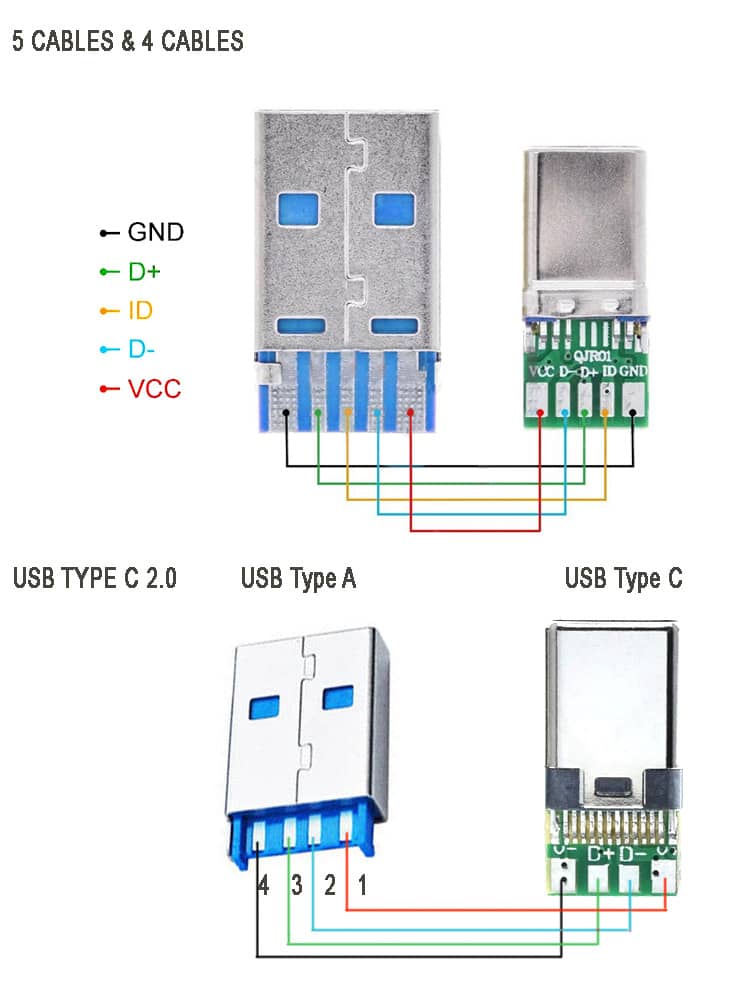
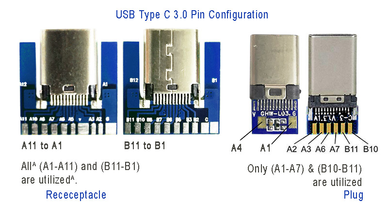
To the left in the above image are USB connectors with board as a USB 2.0 mode utilization, (D+, D-, VBUS, GND). Note that the USB 3.0 are fully functional cables connections are implemented with 8 or 10 connecting wires/bus.
The 24-pin double-sided connector offers a USB-C port that measures 8.4 x 2.6 x 6.65 mm. The 8.4 millimeters (~0.33 inches) is its width, the 2.6 millimeters (~0.10 inches) is its height, and the depth of 6.65 millimeters (~0.262 inches). The dimensions are for the internal side of a receptacle and outer side of a plug. And for more details refer to the datasheet provided by the manufacturer.
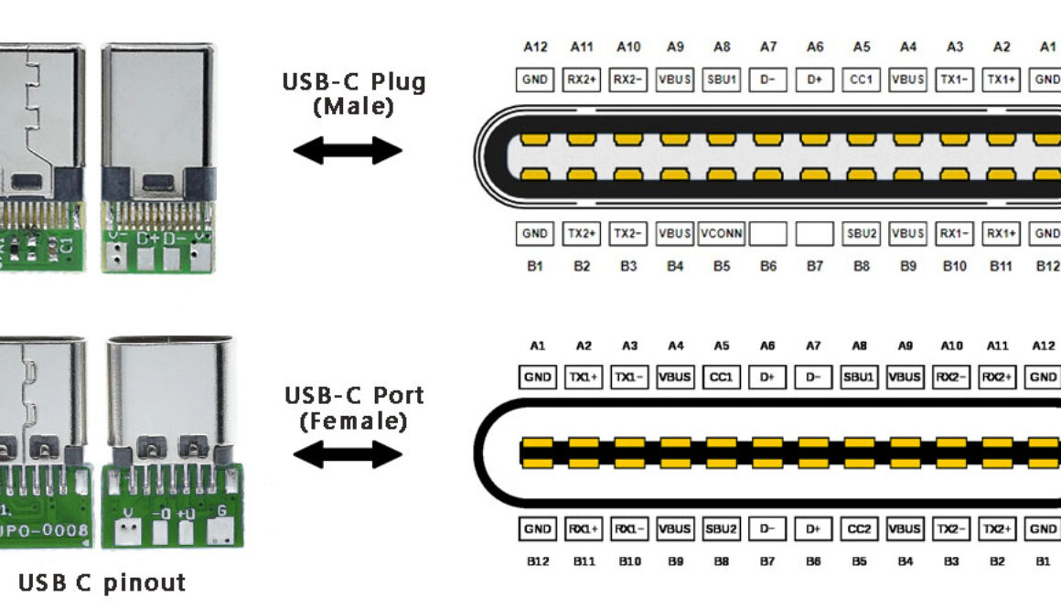
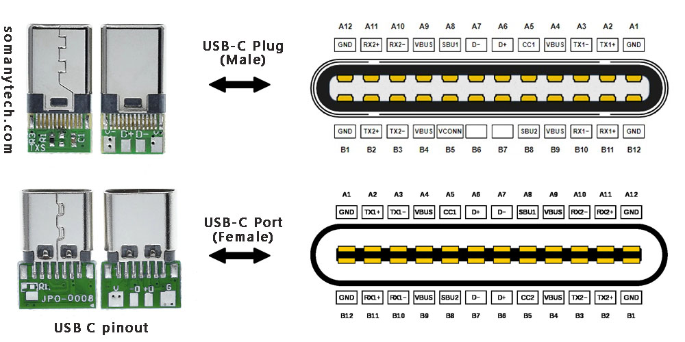
These connectors come in two forms: a male/ plug and a female/ receptacle. (see image above)
The Plugs are commonly found on cables and adapters, providing the means to connect devices. On the other hand, receptacles can be found on devices and adapters, providing a socket for the plug to be inserted into and for establishing connections.
Simplified USB C pinout with their functions are as follows:
The USB C pinout table, offering resources on the intricate details of USB-C connectors. By reading the table, you could understand various pins and their vital functions, enabling a comprehensive understanding of how USB-C devices and cables work together in conjunction.
With careful attention to detail, the table unveils an array of essential pins such as VBUS, GND, CC1, CC2, D+, D- and so on. Each pin have a distinct purpose, from power supply and communication channels to data transmission and more.
It’s a complex network of connectivity enclosing power delivery, audio, video, and alternate modes. As you explore USB protocols, you’ll gain a profound insight of the complex signals and connections within the USB-C ecosystem.
Pin
Name
Description
Pin
Name
A1
GND
DC ground (+0V)
B12
GND
A2
TX1+
Super speed data transmit+ (host to device)
B11
TX2+
A3
TX1-
Super speed data transmit- (device to host)
B10
TX2-
A4
VDD
DC power (+5V)
B9
VDD
A5
CC1
Power delivery communication line
B8
CC2
A6
D+
Data transmit (host to device)
B7
D+
A7
D-
Data transmit (device to host)
B6
D-
A8
SBU1
Secondary bus
B5
SBU2
A9
VDD
DC power (+5V)
B4
VDD
A10
RX2-
Super speed data receive- (device to host)
B3
RX1-
A11
RX2+
Super speed data receive+ (host to device)
B2
RX1+
A12
GND
DC ground (+0V)
B1
GND
Below is an image showing USB type C 3.0 modules for high speed data communication:
Power: The A4, B4 and A9, B9 are connected to supply voltage. Also A1, B1 and A12, B12 are grounded. Thus, number of pins and wires to GND and VCC are reduced to 2 only.
SBU1, SUB2: These pins are called secondary bus. The A8, B8 are for side-band and are not utilized in USB communication and are reserved for future use. And therefore, the functional pins on each side remains to 9 each.
CC1 or CC2: These pins are used for Pin configuration detection, CC is used for USB-PD, i.e. USB power delivery communication to determine current control to the devices, for example charging current. Generally, CC is connected in series with a Resistor = 56k at port end. Thus, the total wires in the cable is found to be minimum 8 in numbers for functional high-speed USB C 3.0/ 3.1 type.
These cable supports both power and data transfer, there are also power only charging cables that support only charging. Meaning, you cannot use them for tasks such as syncing devices, transferring files, or connecting peripherals. They are solely intended for charging purposes. They come with only two connecting wires inside, and they are thicker wires to offer lower resistance to the current flowing though them.
These are made to target devices like neckband/ earphone charging, for charging mobile-phones, USB powered LED lamps and other gadgets that have nothing to do with the data transfer. They are less expensive than the one with data sync capability.
We need correct LED resistor value to ensure that the LED operates at the desired brightness level and doesn’t get damaged by excessive series current though it. In this article, we will explore the resistor values for different color LEDs for different common voltage values.
These values below are calculated based on generally documented forward voltages for the Red (R)- 2.0 Volts, Green (G)- 2.5 Volts, Blue (B)- 3.3 Volts, White (W)- 3.5 Volts, LEDs and forward current @ 20mA for maximum brightness. These values are calculated and tested for working within safe operating points and can be used for any circuit and any projects.
First select the supply voltage or Source voltage (Vs). Now pick the corresponding optimal value of (R) Resistor. You can choose any resistor value from minimum, maximum and optimal value, optimal being recommended.
It’s important to understand the relation between LED life and current while selecting the resistor’s values for an LED. More than optimal current through the LED shortens the operating life of the LED.
Also over-current/ over-voltage causes immediate permanent damage and fuses the diode permanently. On the contrary, insufficient current or you can say under-current can result in a dimmed LED or one that does not glow at all.
Optimal Value and Efficiency
By selecting the optimal LED resistor value, it can help to increase the efficiency and minimize power consumption. This is very important to choose a LED resistor value that limits the extra current in the case if the circuit is portable and battery operated. This can help to extend the life of the device and reduce charging recharging of the circuit.
Below values are for near optimal values for working in highly efficient ways. It saves a lot of power of battery operated devices as it gives near maximum brightness at lower current which is helpful in LED indicator applications.
These LED resistor chart values below are calculated based on generally documented forward voltages for the Red (R)- 2.0 Volts, Green (G)- 2.5 Volts, Blue (B)- 3.3 Volts, White (W)- 3.5 Volts LEDs and forward current @ 15mA for near maximum brightness.
First select the supply voltage or Source voltage (Vs). Now pick the corresponding optimal value of (R) Resistor. You can choose any resistor value from minimum, maximum and optimal value, optimal being recommended.
Input Voltage
LED color
Min. Value of Resistor
Optimal Value of Resistor @15mA
Max. Value of resistor
3V
R
62 Ω
68 Ω
65 Ω
G
30 Ω
33 Ω
36 Ω
B
-
-
-
W
-
-
-
3.7V
R
100 Ω
110 Ω
120 Ω
G
75 Ω
82 Ω
91 Ω
B
24 Ω
27 Ω
30 Ω
W
10 Ω
13 Ω
15 Ω
4.2V
R
130 Ω
150 Ω
160 Ω
G
100 Ω
110 Ω
120 Ω
B
56 Ω
62 Ω
68 Ω
W
43 Ω
47 Ω
51 Ω
5V
R
180 Ω
200 Ω
220 Ω
G
150 Ω
160 Ω
180 Ω
B
100 Ω
110 Ω
120 Ω
W
91 Ω
100 Ω
110 Ω
6V
R
240 Ω
270 Ω
300 Ω
G
220 Ω
240 Ω
270 Ω
B
160 Ω
180 Ω
200 Ω
W
150 Ω
160 Ω
180 Ω
9V
R
430 Ω
470 Ω
510 Ω
G
390 Ω
430 Ω
470 Ω
B
360 Ω
390 Ω
430 Ω
W
330 Ω
360 Ω
390 Ω
12V
R
620 Ω
680 Ω
750 Ω
G
560 Ω
620 Ω
680 Ω
B
510 Ω
560 Ω
620 Ω
W
510 Ω
560 Ω
620 Ω
24V
R
1.3 KΩ
1.5 KΩ
1.6 KΩ
G
1.3 KΩ
1.5 KΩ
1.6 KΩ
B
1.2 KΩ
1.3 KΩ
1.5 KΩ
W
1.2 KΩ
1.3 KΩ
1.5 KΩ
By selecting the correct resistor values, you can ensure that your LED circuit operates at the desired brightness level, is efficient, and offers the minimal power dissipation. And thus while designing an LED circuit for critical applications, be sure to refer to the datasheet for specific LED to determine the appropriate operating values.