What is 180 motor? Many times you might have seen 180 written on DC motor. But many people don’t know what actually 180 dc motor is apart from it is a motor used in various RC toys/ projects and DIY kits.
The 180 model of DC motor represents certain ‘dimensions’ of the motor body. This dimension is standard for all 180 motor.
The number 180 is the Size ID of motor standardized for maufacturers.
This body or casing of the motor is generally made up of nickel-coated steel, along with some plastic parts as an accessory. It is a medium torque medium power device for low to mid-power applications generally in robotics and RC cars.
Following table showing specs/ specification of 180 motor:
Component name
180 dc motor
Category
Electro-mechanical dc motor
Motor body size
(std.)
3.15 × 2.02 × 1.54 cm
Shaft diameter
(std.)
0.2 cm or (2 mm)
Shaft length
(generally)*
5 mm - 15 mm
Operating voltage
3.7 - 8.0 volts
Rated voltage
6 volts
No load current
(non std.)
0.45 - 0.74 A
Speed (non std.)*
Speed at 3 volt
~1500 rpm
Speed at 6 volt
~3200 rpm
Commutation
Brushed/ Brush-less
Description:
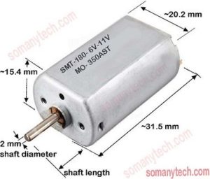
The 180 dc motors have a standard size of 31.5 x 20.2 x 15.4 mm, this is the outer frame size of it. The number 180 is the indicator of it. It is same to the number as that of 775 motor.
The shaft size of 2 mm is standard and widely used by almost all manufacturers. The length of the shaft varies according to the application from 6 mm to 15 mm, but a 9 mm shaft is most common.
The rpm of the motor is directly proportional to the voltage of operation and rpm to be calibrated as per the requirement of the project. Its nominal operating voltage range is 3 volts to 8 volts.
No-load current shows how much current the motor consumes while there is no load connected to it. It also indicated the motor power requirement for working. No-load current is max. current that can be used by the motor.
The speed of such dc motors ranges from 29000 rpm to 34000 rpm at 6 volts depends on technology and manufacturers specs, and near proportional thereafter increase in voltages.
Both brushed and brushless model can be at found online stores. Brushed motor are cheaper in Comparision to brushless motor.
The 150 ohm Resistor color code for 4-band resistor is as shown in the image below:
[Brown, Green, Brown, Gold]
Band
Color
Value
1st Brown
1
2nd Green
5
3rd Brown
10
4th gold
5%
150±5% Ω
150 ohm resistor color code for 4-band is calculated as:
(1st digit) = Brown = 1
(2nd digit) = Green = 5
(multiplier) = Brown = 1 = 10^1 = 10
(tolerance) = Gold= ±5%
∴ 15×10±5% –> 150 ohms –> 150 Ω ∴ the real value of 150 Ω resistor is between 142.5 Ω to 157.5 Ω
Description: From the resistor color code table we have to find the color code of resistor according to its decimal value of each band counted from left to right.
Thus, for 120 ohm resistor, 1st digit is ‘ 1 ‘, ∴ look for color in a chart with value 1, then it’s your 1st color(say brown). The 2nd digit is ‘ 3 ‘, ∴ look for color in a chart with value 2, then it’s your 2nd color (say green).
The 3rd digit ‘1’ (but value 10^1 = 10) is multiplier ‘ 10 ‘, ∴ look for color in table with value 1, then it’s your 3rd color band (say brown).
The last bands in 4th and 5 th bands resistors gives the tolerance value of the resistor. In that, the Gold band indicates a 5% tolerance of the resistor value. For Silverband, it is 10%, and Brown its value points at 1% tolerance. If the 4th color band is absent then it is assumed to be 20% tolerance.
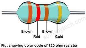
The 120 ohm Resistor color code for 4-band resistor is as shown in the image below:
120 ohm Resistor color code for 4-band is:
[Brown, Red, Brown, Gold]
Band
Color
Value
1st Brown
1
2nd Red
2
3rd Brown
10
4th gold
5%
120±5% Ω
120 ohm resistor color code for 4-band is calculated as:
(1st digit) = Brown = 1
(2nd digit) = Red = 2
(multiplier) = Brown = 1 = 10^1 = 10
(tolerance) = Gold= ±5%
∴ 12×10±5% –> 120 ohms –> 120 Ω ∴ the real value of 120 ohm resistor is between 114 Ω to 126 Ω
Description: From the resistor color code table we need to find the color code of resistor with respect to its decimal value of the each band counted from left to right.
Thus, for 120 ohm resistor, 1st digit is ‘ 1 ‘, ∴ look for color in a chart with value 1, then it’s your 1st color(say brown). The next 2nd digit is ‘ 2 ‘, ∴ look for color in a chart with value 2, then it’s your 2nd color (say red).
Next 3rd digit ‘1’ (but value 10^1 = 10) is multiplier ‘ 10 ‘, ∴ look for color in a chart with value 1, then it’s your 3rd color band (say brown).
The last bands in 4th and 5th bands resistors gives the tolerance value of the resistor. Here, the Gold indicates a 5% tolerance of the resistor value. For Silver, it is 10%, and Brown it is value points at 1% tolerance value. If the 4th band is absent then it is assumed as 20%tolerance.
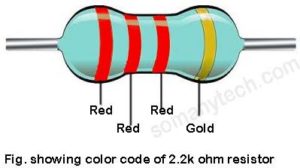
The 2.2k ohm Resistor color code for 4-band resistor is as shown in the image below:
2.2 k ohm resistor color code is:
[ Red, Red, Red, Gold ]
Band
Color
Value
1st Red
2
2nd Red
2
3rd Red
100
4th gold
5%
2.2k±5% Ω
2.2k ohm resistor color code for 4-band is calculated as:
(1st digit) = Red = 2
(2nd digit) = Red = 2
(multiplier) = Red = 2 = 10^2 = 100
(tolerance) = Gold= ±5%
∴ 22×100±5% –> 2.2k ohms –> 2200 Ω ∴ the real value of 2.2k ohm resistor is between 2090 Ω to 2310 Ω
Description: From the resistor color code table we need to find the color code of resistor with respect to its decimal value of the each band counted from left to right.
Thus, for 2.2k ohm resistor, 1st digit is ‘ 2 ‘, ∴ look for color in a chart with value 2, then it’s your 1st color(say red). The next 2nd digit is ‘ 2 ‘, ∴ look for color in a chart with value 2, then it’s your 2nd color (say red). Next 3rd digit ‘100’ (but value 10^2 = 100) is multiplier ‘ 2 ‘, ∴ look for color in a chart with value 2, thenit’s your 3rd color band (say red).
The last bands in 4/5 th bands resistors shows the tolerance value of the resistor. Here, the Gold indicates a 5% tolerance value. For Silver, its values is 10%, and Brown it is value at 1% tolerance. If the 4th band is absent then it is taken as 20% tolerance.
1 ohm resistor color code can be found using the resistor color code chart, below image showing a resistor color code of 1Ω 4-band resistor:
[Brown, Black, Gold, Gold (any) ]
The color code in tabular form for the 1R four-band resistor is brown, black, gold, gold.
Band
Color
Value
1st Brown
1
2nd Black
0
3rd gold
0.1
4th gold
+-5%
1st digit 1
2nd digit 0
3rd multiplier:
0.1
1 Ohm
tolerance:
+-5%
4-band 100 ohm resistor color code is calculated as:
1st-band= Brown= 1 (1st digit)
2nd-band= Black= 0 (2nd digit)
3rd-band= Brown= 0.1 (multiplier) = 0.1
4th-band= Gold= ±5% (tolerance) – {4th band can be of any color as it indicates tolerence value}
Thus, 10×0.1±5% –> 1 ohm –> 1 Ω
The tolerance will be –> 5% of 1 –>0.05 Ω
Theoretically, the value of 1 Ω resistor is between 0.95 Ω to 1.05 Ω
Description: From the chart we got the color code of resistor with respect to the decimal value of the respective band counted from left to right. So for 1-ohm resistor, 1st digit is ‘ 1 ‘, ∴ look for colour in chart having value 1, then it’s 1st color will be brown. The next 2nd digit is ‘ 0 ‘, ∴ look for color in chart having value 0, then it’s your 2nd color will be black. Next 3rd one is multiplier 0.1 ∴ look for color in chart having value 0.1, then it’s your 3rd color will be gold.
The last band in 4 and 5-bands resistors is the markings for tolerance value in the resistor. In this case, it is Gold which indicates a 5% tolerance value. For Silver, it is 10%, Black indicates 1% and 2% tolerance is indicated by Brown. If the 4th band is absent it should be considered as 20% tolerance.
Image showing 1 ohm resistor color code of 5-band resistor:
[Brown, Black, Black, Silver, Black]
The 100R 5-band resistor color code is brown, black, black, silver, black and it is found as:
1st-band = Brown= 1 (1st-digit)
2nd-band = Black= 0 (2nd-digit)
3rd-band = Black = 0 (3rd-digit)
4th-band = Silver = 0.01 (multiplier) = 0.01
5th-band = Black= ±1% (tolerance)
Description:
So for 1-ohm 5-band resistor which comes under precision resistor,
The 1st digit is ‘ 1 ‘, ∴ look for color in table having value 1, then it’s your 1st color- brown.
Next 2nd digit is ‘ 0 ‘, ∴ look for color in chart having value 0, then it is 2nd band color- black.
Its 3rd digit is ‘ 0 ‘, ∴ look for color in chart having value 0, then it is 3rd band color- black.
Now, 4th digit is multiplier that should be (0.01), therefore, 4th band will be of silver color.
Characteristics will be the same from the value to the power rating of 5-band resistor and 4-band resistance except the bands color and some times the tolerance value.
Click here! to Brush-up resistors color code table and method to find their value.
A precision resistor is a normal resistor with near accurate Ohmic values. Technically they have very low tolerance value as compared to the normal resistors.
The lower the value of tolerance of the resistor shows the lower deviation from resistor value and higher the value of tolerance the higher the deviation from the actual standard value.
The Precision resistor is also called a film resistor or foil resistor.
The tolerance value is indicated in percentage (%).
You can say that if the tolerance value of the resistor is below 1% it can be classified under precision resistor, they have the tolerance in the range of 0.005%, 0.025%, 0.1%, 0.01%, etc
There are some other factors that are also considered while considering the precision in the resistance that will be discussed below in detail.
The resistance with the tolerance value 10%, 20%, 5% does not fall under the Precision resistor.
Observe the difference among various tolerance values of the resistor and resultant value of resistor:
10k resistor 10% tolerance = 9000 to 11000 Ω
10k resistor 5% tolerance = 9500 to 10500 Ω
10k resistor 1% tolerance = 9900 to 10100 Ω
10k resistor 0.005% tolerance = 9999.5 to 10000.5 Ω
From the above observation, we can say that the nominal value of the resistor is between this two range and tolerance value play a great role if accuracy matters in your circuit.
Important factors of precision resistors:
Technology involved: Wire-wound, Metal Film, Metal Foil, Bare Metal, Thin Film. All technology gives different results in resistor performance.
Temperature coefficient ( ppm/°C ): It is the amount the Resistor value changes for every 1°C change in temperature.
110 ppm/°C means the Resistance increases 110 Ohms for every 1M Ohm resistance for each degree rise in temperature. Or say ratio wise for other values, 11 ohms for every 100k or 1.1 ohm every 10k.
Operating temperature: It indicates the operating temperature range of the resistor in which it remains stable, also can work without being damaged.
Power rating: It indicates the power handling capacity of a resistor without being damaged.
Application of Precision resistor:
Electronic weighing machine/ scales: Electronic weighing machine is two way the object and this purpose should be must be fulfilled with the accuracy, Precision resistor provide that accuracy in the circuit of the weighing machine.
Audio application/ low noise amplifier: Audio device is one of the widely used devices that requires precise very low noise resistors and other components. Highly stable and linear response of Precision resistor Ideal for audio application.
Commercial aviation industry: Highly accurate value of onboard instruments in the airplane is necessary as it operates and handles the critical conditions of such a Mammoth machine.
Measuring instruments and meters: Digital multi-meters, LC meters, audio meters, altimeters, and all sort of measuring instruments install Precision resistors who has to give the measured value of a particular physical or electrical condition.
Precision Resistor color code: 5 band resistor color code and 6 band resistor color code
5 band and 6 band resistor color Code is generally used to indicate the color code of Precision resistors, the following table showing 5/ 6 band resistor color code:
The 330 ohm Resistor color code for 4-band resistor is as shown in the image below:
[Orange, orange, brown, gold]
Band
Color
Value
1st Orange
3
2nd Orange
3
3rd Brown
10
4th gold
+-5%
1st digit 3
2nd digit 3
3rd multiplier:
10
330 Ohm
tolerance:
+-5%
330 ohm resistor color code for 4-band is calculated as:
(1st digit) = Orange = 3
(2nd digit) = Orange = 3
(multiplier) = Brown = 1 = 10^1 = 10
(tolerance) = Gold= ±5%
∴ 33×10±5% –> 330 ohms –> 330 Ω ∴ the real value of 330 Ω resistor is between 313.5 Ω to 346.5 Ω
Description: From the resistor color code table we found the color code of resistor with respect to its decimal value of the respective bands counted from left to right. Thus, for 330-ohm resistor, 1st digit is ‘ 3 ‘, ∴ look for color in a chart with value 3, then it’s your 1st color(say orange). The next 2nd digit is ‘ 3 ‘, ∴ look for color in a chart with value 3, then it’s your 2nd color (say orange). Next 3rd digit ‘0’ (but value 10^1 = 10) is multiplier ‘ 1 ‘, ∴ look for color in a chart with value 1, then it’s your 3rd color band (say brown).
The last bands in 4 or 5-bands resistors are the indicator of the tolerance value of the resistor. Here, it is Gold that indicates a 5% tolerance value. For Silver, its values counts 10%, and Brown it is value at 1% tolerance. If the 4th band is absent it is taken as 20% tolerance value.
The 470 ohm Resistor color code for 4-band is as shown in the image below:
[Yellow, Violet, Brown, Gold]
Band
Color
Value
1st yellow
4
2nd violet
7
3rd brown
10
4th gold
5%
470±5% Ω
470 ohm resistor color code for 4-band is calculated as:
(1st digit) = Yellow = 4
(2nd digit) = Violet = 7
(multiplier) = Brown = 1 = 10^1 = 10
(tolerance) = Gold= ±5%
∴ 47×10±5% –> 470 ohms –> 470 Ω ∴ the real value of 470 Ω resistor is between 446.5 Ω to 493.5 Ω
Description: From the resistor code chart we found the color code of resistor with respect to the decimal value of the respective band counted from left to right. So for 470-ohm resistor, 1st digit is ‘ 4 ‘, ∴ look for color in a chart with value 4, then it’s your 1st color(say yellow). The next 2nd digit is ‘ 7 ‘, ∴ look for color in a chart with value 7, then it’s your 2nd color (say violet). Next 3rd digit ‘0’ (but value 10^1 = 10) is multiplier ‘ 1 ‘, ∴ look for color in a chart with value 1, then it’s your 3rd color band (say brown).
The last bands in 4 or 5-bands resistors are the indicator of the tolerance value of the resistor. Here, it is Gold indicates a 5% tolerance value. For Silver, its values is 10%, and Brown indicates 1% tolerance. If the 4th band is absent it is considered in 20% tolerance value.
SMD capacitors most extensively used for capacitor requirements on the PCB which are perfect for large scale manufacturing. SMD capacitor one of the derivatives of SMT (surface mount technology) having small and easy to place components which enhances the manufacturing speed.
Ceramic, tantalum, electrolytic capacitors are few of the available options when it comes to SMD capacitor. ceramic capacitors are easy and cost-effective to manufacture and thus most widely used.
If you want to go through the detail of the capacitor and their types along with its working then click here!
What is an SMD capacitor?
SMD capacitor is nothing but a capacitor with compact size and no long lead. It is developed in such a way that it offers an advantage for mass production of electronic devices and equipment, along with some technical advantage in the operation of high-frequency devices.
Advantage of SMD capacitor:
SMD capacitor has no leads or very short lead, the inductive effect of leads are avoided ( its importance comes into the picture when we are working on high-frequency circuits and radio circuits ‘RF range’). Eg. while designing a tank circuit using LC, if the leads of the capacitor are not kept short then it will oscillate at different frequencies than that we have designed.
The size of the surface mount capacitor is smaller than the traditional capacitor space and the device can be confined in a smaller area, useful in portable devices.
An increase in the manufacturing speed, therefore, reduction in cost is possible.
Due to the standard size, it is much easier to handle and place on PCB using the robotic assembly process.
Disadvantage of SMD capacitor:
Its advantages have an upper hand than that of disadvantages. Why we are saying its disadvantages are very few and can be neglected.
One disadvantage is its size when it comes to repairing. Suppose you’re considering to replace it then it is a little bit arduous work.
Lower heat capacity of a smaller capacitor can damage it if proper cooling ventilation is not given. Surface mount components lower operating temperatures than the traditional one.
Common capacitor value with codes in a chart:
Common capacitor value for SMD capacitor is almost same as ceramic and electrolytic capacitors. Below table have all the common capacitor values listed that are useful for you.
For code “104″ The two figures 10 indicate the significant figures and the 4 indicates the multiplier , i.e. 10^4 = 10000.
Therefore, the value comes out to be 100000 pf = 0.1 uf
There is a certain range of capacitors which is very commonly used with PCB and in the circuits. The common capacitor code is given below so that it is easier to remind it whenever required while studying or designing the circuits:
Capacitor (104)
Capacitor (108)
100 nF
0.1 pF
Capacitor (154)
Capacitor (158)
150 nF
0.15 pF
Capacitor (224)
Capacitor (228)
220 nF
0.22 pF
Capacitor (334)
Capacitor (338)
330 nF
0.33 pF
Capacitor (474)
Capacitor (478)
470 nF
0.47 pF
Capacitor (684)
Capacitor (688)
680 nF
0.68 pF
Capacitor (105)
Capacitor (109)
1.0 μF
1.0 pF
Capacitor (155)
Capacitor (159)
1.5 μF
1.5 pF
Capacitor (479)
Capacitor (229)
4.7 pF
2.2 pF
Capacitor (689)
Capacitor (339)
6.8 pF
3.3 pF
Capacitor (100)
Capacitor (103)
10 pF
10 nF
Capacitor (150)
Capacitor (153)
15 pF
15 nF
Capacitor (220)
Capacitor (223)
22 pF
22 nF
Capacitor (330)
Capacitor (333)
33 pF
33 nF
Capacitor (470)
Capacitor (473)
47 pF
47 nF
Capacitor (680)
Capacitor (683)
68 pF
68 nF
Capacitor (101)
Capacitor (681)
100 pF
680 pF
Capacitor (151)
Capacitor (102)
150 pF
1000 pF [1.0 nF]
Capacitor (221)
Capacitor (152)
220 pF
1500 pF [1.5 nF]
Capacitor (331)
Capacitor (222)
330 pF
2200 pF [2.2 nF]
Capacitor (471)
Capacitor (682)
470 pF
6800 pF [6.8 nF]
Capacitor (332)
Capacitor (472)
3300 pF [3.3 nF]
4700 pF [4.7 nF]
Capacitor (225)
Capacitor (335)
2.2 μF [2200 nF]
3.3 μF [3300 nF]
Capacitor (475)
Capacitor (685)
4.7 μF [4700 nF]
6.8 μF [6800 nF]
SMD capacitor size:
SMD capacitor’s size certainly depends on their types, their size a different for electrolyte capacitor and ceramic capacitor. Below are some SMD capacitor size standards for different types of SMD capacitor:
Size Code (mm)
Size (in mm)
Size Code (inches)
Size (in inches)
1005
1.0 × 0.5
0402
0.04 × 0.02
1608
1.6 × 0.8
0603
0.06 × 0.03
2012
2.0 × 1.2
0805
0.08 × 0.05
3216
3.2 × 1.6
1206
0.126 × 0.063
3225
3.2 × 2.5
1210
0.12 × 0.10
4520
4.5 × 2.0
1808
0.18 × 0.08
4532
4.5 × 3.2
1812
1.8 × 0.12
5750
5.7 × 5.0
2220
0.22 × 0.20
Are SMD capacitor polarized?
YES, SMD capacitors are polarized but not all SMD capacitors are polarized. The electrolytic SMD capacitor compulsorily comes with the polarity and has its dedicated applications.
They are normally yellow and black color with markings on it.
How to identify SMD capacitor polarity?
The polarity of surface mount capacitors is marked by a white or black line at one of the ends of the device. Note that on a rounded surface mount capacitor the small black corner indicates the negative side. This line/bar indicates the positive terminal of the capacitors as shown in the figure above.
How do you know the capacitor is nonpolar?
If no indication like a bar or colored dash is present on the capacitor then it is a nonpolar capacitor. This nonpolar ceramic capacitor generally brown, yellowish-brown or grey in color.
SMD resistors are generally black in color.
How to test a SMD capacitor?
If your surface mount capacitor does not have a code written on it then follow the following steps:
Step1– Remove your capacitor from the PCB ( it is not possible to test the component without removing it from the board)
Step2-Put your multimeter to the Mega-ohm range. And connect the positive of multimeter to the positive of a capacitor and negative to the negative of a capacitor (if it is polarised capacitor). If your capacitor is non-polarized then no issue of polarity.
Step3 – Now observe the value Of the component,
If it is showing few Megaohms and decreasing slowly then your capacitor is faulty.
If it is showing few Megaohms, increasing slowly and becomes steady (or not showing any value due to out of range), then the capacitor is good. There is no need to replace it.
Insertion loss and return loss are widely used terms in the field of microwave technologies. Insertion loss and return loss plays an important role in designing and development of high-frequency devices such as filters, power dividers, amplifier, etc.
These are quite similar concepts, it is an advanced form of the basic electronics we have learned in network theorems.
What is an insertion loss?
Technically, when some system or circuit is inserted between a source and a load, some of the signal power from the source is dissipated through the circuit components due to their resistive nature that results in losses.Therefore, not all the transmitted signal power is transferred to the load when the load is connected to the source. The losses thus occurred is called Insertion Loss.
It is a very important factor while designing and implementing microwave circuits. It is generally expressed in (dB) decibels.
If the power transmitted to the load is PT and the incident power received by the load is PR, then the insertion loss is given by:
What is a return loss?
Practical circuit realization always suffers a certain level of mismatch between the impedance of the signal source and a load of a system (this load can be a transmission, line antenna, system filters or any device system).Some fraction of signal power inserted is reflected back due to mismatch between two systems, this fraction of power loss is called return loss.
Less power reflection is desirable thus high return loss (RL) is considered good according to the formula:
where RL is the return-loss in dB, Pi is the incident power to the system and Pr is the reflected power from the system.
Figure showing insertion loss offered by a bandpass filter, the required signal at another end will have some power loss:
What causes insertion loss?
Insertion loss causes due to two factors namely ohmic loss, dielectric leakage and the return loss is caused due to mismatched systems.
The first-factor ohmic loss is an unavoidable loss as it is a property of conductor used for connecting the components and the resistor used. Thus, to reduce ohmic losses the components are placed very closely integrated into a small confined area. VLSI and ULSI technology are used for making an integrated circuit that offers high efficiencies.
In the case of a capacitor, there is some leakage current through it can be reduced but cannot be omitted ideally. This is because of the dielectric in it, thus resulting in power loss.
Miss-matched in the system results in insertion loss and return loss. Ideally reflected power must be equal to zero but, in a practical sense, it has some value that can be up to 10 dB or more even after minimizing these losses.
As the frequency increases insertion loss and return loss are more relevant in the systems due to the characteristics of microwave frequencies. The voltage standing wave ratio (VSWR) and reflection coefficient (Γ) are an important factor involved in return loss.
Its basic version we have already learned in the Network theorems. The Maximum Power Transfer Theorem is significantly applicable in microwave frequencies, as the signal power one of the most considered and important factors in RF circuits while designing and implementing filters, amplifiers & power dividers.
The MPT states that the maximum power is transferred from one circuit to another circuit (or one system to another system) when the impedance of the source is equal to the impedance of the Load.
For maximum power transfer, Xs = Xl
This can be seen as,
When the source impedance is matched with load impedance then ideally return loss must be equal to zero. But practically, it has some value that can be up to 10 dB or more even if the system is matched.
Importance:
Suppose that you have to transmit a signal through an RF remote control device operating on a small battery. The battery capacity of the remote control is generally very less as remote control must be portable and lite in weight, also long operating hours are expected.
We need to increase the efficiency of the transmitter used in remote control ultimately do we need to reduce the return loss and insertion loss in the system used in the circuit.Also, the power generated by the transmitter must be efficiently transmitted by the antenna and therefore requires proper impedance matching of output ports of source and the antenna.
It has its applications in the RF sector like Radars and satellite phones.
Relation with the scattering parameter:
Below image showing insertion loss and return loss for a 90MHz highpass filter matched at 50 Ohms.:
Insertion loss and return loss are linked with the scattering perimeter when the source and the load of the system is matched to the same reference impedance (say 50 Ohms).
S parameters are is the modern way of analyzing two-port networks. It is very helpful in in in optimizing the circuit to its best. It is capable of determining even smaller return loss and insertion loss in the form of s-parameters namely S11, S22, S12, S21:
S12 = transmission coefficient (power gain in dB of the system in a forward direction)
S21 = transmission coefficient (power gain in dB of the system in reverse direction)
S11 = reflection coefficient (related to return loss in dB at port 1)
S22 = reflection coefficient (related to return loss in dB at port 2)
For perfectly matched and ideal n/w:
→ S11 = S22 = 0
-→ S12 = minimum
–→ S21 = depends on the nature of the circuit (≥0)


")


