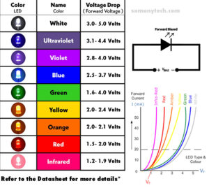
Below is the LED Voltage Calculator for all color LED, as they becoming popular and irreplaceable for the source of light and indicators. One of the key considerations when working with LEDs circuit is determining the correct forward voltage required for that specific LED circuit. The voltage requirements for LEDs can vary based on the color of the LED. In this article, we will explore the different voltage requirements for different colored LEDs.
LED Voltage Calculator
It is IMPORTANT that if you have the datasheet available with you then refer the (Vf) forward voltage from datasheet for more precise consideration. The values calculated using LED voltage calculator on this page are safe and nominal values for respective color of diodes. All the values calculated are applicable to SMD LEDs as well.
What is an LED Voltage Calculator?
An LED voltage calculator is an online tool that helps you to calculate the forward voltage required for particular color of LED. By inputting color of led, the calculator can quickly and accurately determine the optimal voltage required for a single LED. Also provides you the operating voltage range, the voltage range in which the LED can be used without getting burnt.
Also, series LED Resistor Calculator Here !! (link)
It is important:
to choose a power supply voltage that is higher than the LED’s forward voltage drop to ensure that it operates at the desired brightness level.
it’s important to choose a resistor that can limit the current to the desired level and prevent damage to the LED.
Red LEDs
Red LEDs are one of the most common types of LEDs used in lighting applications. They typically have a voltage range of 1.5- 2.1 volts.
Green LEDs
Green LEDs are another popular option for lighting. They typically have a voltage range of 1.6- 4.0 volts.
Blue LEDs
Blue LEDs are a newer type of LED that have gained popularity in recent years. They typically have a voltage range of 2.5- 3.7 volts.
Yellow LEDs
Yellow LEDs are a newer type of LED that have gained popularity in recent years. They typically have a voltage range of 2.0-2.4 volts.
White LEDs
White LEDs are a popular choice for domestic lighting applications because they offer a bright and uniform light output. They typically have a voltage range of 3.0-5.0 volts.
RGB LEDs
RGB LEDs are a type of LED that can emit different colors depending on the voltage applied to each of the three pins. They typically have a voltage range of 3.5-5.0 volts for each individual color and overall works on 3.0-5.0V. When working with RGB LEDs, it’s important to choose a power supply voltage that is higher than the highest forward voltage drop of the three individual colors.
In conclusion, remembering the forward voltage different colored LEDs is important for anyone working with LEDs. By selecting the correct voltage, you can ensure that your LEDs operate at the desired brightness level as well as your circuit is efficient in terms of power consumption. When designing an LED circuit, be sure to consult the datasheet for your specific LED to determine the maximum operating ratings.
This series LED resistor calculator comes handy when you have a single LED of the same color or different color of LEDs and need to know which resistor you should use. This calculator will give you the value of series LED resistance that could be used in series with an LED to prevent it from damaging due to over current.
One of the features of this calculator is that it will also give you power dissipation due to LED as well as resistor. Also suggests the Standard Value of Resistor according to E3, E6, E12, E24, so that you can directly use the nearest available standard resistors.
To use this calculator, enter three known values (Vs, Vf, If) and press “Calculate” to solve for the others.
Power Dissipation is calculated considering the actual calculated value of ‘R’. When using the standard value of resistor, consider the selected value for Power Dissipation calculation.
PL = Vf x If <for LED>
PR = R x I^2 <for Resistor>
To calculate the resistor value manually or theoretically, needed for a simple LED circuit, apply Ohm’s Law, then substitute parameters.
V = I x R —<ohm’s law>
Vs = Vr + Vf —<total voltage drop>
Vs = Ir.R + Vf —<Vr = Ir.R>
Ir.R = Vs – Vf —<adjusting the eq.>
R = (Vs – Vf )/Ir —<we know that Ir= If >
R = (Vs – Vf )/If —<final result>
So the equations…
where:
VS is the source voltage, measured in volts (V),
Vf is the forward voltage across the LED, measured in volts (V),
Ir = the the current through the Resistor*, measured in Ampere (A), and
If = the current through the LED*, measured in Ampere (A), and
Rs = R is the current limiting series resistor, measured in Ohms (Ω).
* All the components are in series, thus the current through the circuit will be the same. Therefore, “If = Ir” = the current through the Resistor = the current through LED
This calculator is a fundamental application of Ohm’s Law Calculations, adding the consideration of the voltage drop from the LED.
This is an online voltage divider calculator 3 resistor and 2 resistor that can make the task of calculations much simpler. In this article, we’ll discuss voltage divider calculators and how to use them.
Voltage divider circuits are a fundamental part of the electronics and electrical engineering field. It is used to divide a given input voltage signal into the required level of voltage, means making it appropriate for different applications within the circuit. A voltage divider circuit consists of two or more resistors connected in series, with a given input voltage applied across these series resistor networks. And the output voltage is taken across one of the resistors. The output voltage is proportional to the value of the resistor across which it is measured.
Voltage Divider Calculator
Explanation:
The voltage divider is a simple circuit that is used in a variety of applications. It is commonly used to create reference voltages or to reduce the voltage of a power supply to a level that is suitable for an electronic circuit. The voltage across R2 can be calculated using the following formula:
Vout = Vs x (R2 / (R1 + R2))
where,
Vs = Vin = is the applied source voltage or input voltage, SI unit is volts (V)
R1 = is the resistance of 1st resistance, SI unit is (Ω)
R2 = is the resistance of 2nd resistance, SI unit is (Ω)
Vout = is the output voltage or voltage across R2, SI unit is volts (V)
The circuit consists of two resistors, R1 and R2, connected in series across a voltage source or lets say input voltage, Vs = Vin. The output voltage is taken across resistor R2. This formula is known as the voltage divider formula. It shows that the output voltage is directly proportional to R2 and inversely proportional to the sum of R1 and R2.
Explanation:
The voltage across R3 can be calculated using the following formula:
Vout = Vs x (R3 / (R1 + R2 + R3))
where,
Vs = Vin = is the applied source voltage or input voltage, SI unit is volts (V)
R1 = is the resistance of 1st resistance, SI unit is (Ω)
R2 = is the resistance of 2nd resistance, SI unit is (Ω)
R3 = is the resistance of 3st resistance, SI unit is (Ω)
Vout = is the output voltage or voltage across R3, SI unit is volts (V)
The circuit consists of three resistors, R1, R2 and R3, connected in series across a voltage source or lets say input voltage, Vs = Vin. The output voltage is taken across resistor R3.
This formula is known as the voltage divider formula. It shows that the output voltage is directly proportional to R3 and inversely proportional to the sum of R1, R2 and R3. You can calculate voltage drop for each of the resistor in series value HERE!
How to use a voltage divider calculator?
Simply input the values of the resistors and the input voltage or source voltage. Once the inputs are entered, the calculator will compute the output voltage and display the result.
Benefits of Using this tool.
Using a voltage divider calculator offers several benefits. Firstly, it saves time and effort in calculating the output voltage of a voltage divider circuit. The calculator does all the calculations automatically, which eliminates the need for manual calculations. This is particularly useful when designing complex circuits that require multiple voltage divider circuits.
Secondly, using a voltage divider calculator improves the accuracy of the calculations. This ensures that the circuit operates as intended.
Conclusion:
Voltage divider calculators are a useful tool for students with their homework, electrical engineers and hobbyists. It can simplify the process of calculating the output voltage of a voltage divider circuit and save time. By following the steps outlined in this article, you can easily use a voltage divider calculator to calculate the output voltage of your circuit.
The 3-band resistor color code calculator is a helpful online tool that simplifies the process of determining the resistance value of a cylindrical color band resistor. For long period, resistor values are conveyed through color-coded bands painted on the resistor, which could be challenging to read, particularly for those who are not familiar with the color-coding methods. Thankfully, the 4-band resistor color code calculator eliminates the guesswork and facilitates easy determination of resistor values. With this tool, you can enter the color bands of your resistor and get an instant calculation of its resistance value, thus taking the hassle out of resistor value calculations.
To use a 3-band resistor color code calculator, simply enter the colors of each band into the corresponding fields on the calculator from left to right.
3 Band Resistor Color Code Calculator
For example, let’s say you have a resistor with the colors Brown, Black and Red. To calculate the value of this resistor using the 3-band color code calculator, you have to enter “brown” in the 1st field, “black” in the 2nd field, “red” in the 3rd field.
Press the ‘Calculate’ button to get the values. And press the ‘Reset’ button to use it again.
If you are on the way to calculate the 3 band resistor value on paper by looking at its color coded band then you can do so by following information.
Calculating the value of a 3-band resistor :
by looking at the color bands may seem challenging at first, but it’s actually quite simple once you understand how to do it:
Step 1: Identify and Determine the color for each band on resistor
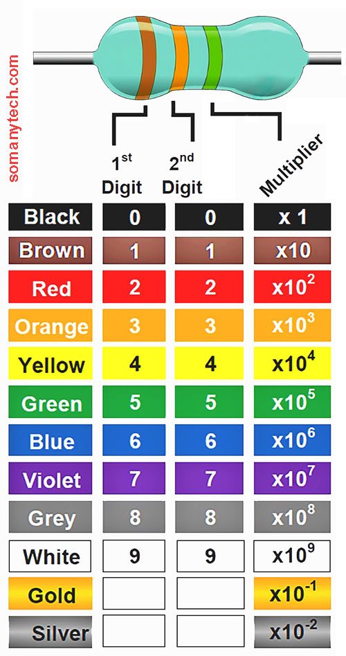
Next, you need to determine the color codes for each of the 3 bands. The color codes for the first two bands represent the resistance value of the resistor. The third band represents the multiplier or number of zeros, and the fourth band is absent here, which represents the tolerance.
Step 2: Calculate the resistance value and tolerance value
In order to calculate the resistor’s resistance value, combine the first two color bands and multiply them by the multiplier value represented by the third band. The absence of fourth band represents the tolerance value of the resistor is ± 20%, which shows the range in which the actual resistance value can vary from the exact value and intended value in %.
For example, if the bands on the body of the resistor are Red, Red and Orange.
Then from the table 1st red band means significant digit of 2, second red band means significant digit 2, third is Orange means multiplier means 10^3, and the 4th Absent means 20% tolerance.
Thus, the resistor value is 22 *10^3 and its tolerance is 20% that is 22 kΩ ± 20%
A 5-band resistor color code calculator is an online tool for getting any resistor value effortlessly. Resistor values are generally represents by color-coded bands printed on the resistor itself, which can be sometimes difficult to decode even if you have remembered the color codes chart in mind. Also, it could be wondering for those who are not familiar with the resistor color code system. By simplifying the value calculations for 5-band resistors, this calculator removes the assumption involved in resistor value calculations.
To use a 5-band resistor color code calculator, simply enter the colors of each band into the corresponding fields on the calculator from left to right.
5 Band Resistor Color Code Calculator
For example, let’s say you have a resistor with the colors Yellow, Violet, Black, Red, and Gold. To calculate the value of this resistor using the 5-band color code calculator, we would enter “Yellow” in the first field, “Violet” in the 2nd field, “Black” in the 3rd field, “Red” in 4th and “gold” in the 5th field.
And press the ‘Calculate’ button to get the values. And press the ‘Reset’ button to use it again.
In case you want to calculate the 5 band resistor value manually based on the color coded bands then you can do so by following these instructions. In brief, a resistor’s value is signified by the first three bands and a multiplier by the fourth band, and the last band denotes the tolerance value.
Calculating the value of a 5-band resistor :
It may seem complicated at first, but once you know how to use the color bands, it’s actually quite simple:
Step 1: Identify and Determine the color for each band on resistor
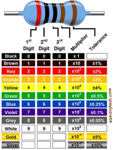
Next, you need to determine the color codes for each of the five bands. The color codes for the first 3 bands indicate the resistance value of the resistor. The 4th band indicates the multiplier value or the number of zeros, and the last band represents the tolerance value.
Step 2: Calculate the resistance value and tolerance value
In order to calculate the resistor’s resistance value, combine the first three color bands and multiply them by the multiplier value represented by the 4th band. In the fifth band, the tolerance of the resistor is shown as a percentage, showing the range between the real and expected resistance values.
For example, if the bands on the body of the resistor are Yellow, Violet, Black, Red, and Gold.
Then from the table 1st Yellow band means significant digit of 4, second Violet band means significant digit 7, third is Black significant digit of 0, fourth Red band means multiplier means 10^2, and the 5th Gold means 5% tolerance.
Thus, the resistor value is 470 *10^2 and its tolerance is 5% that is 47kΩ ±5%
Conclusion:
The 5-band resistor color code calculator is an essential tool for anyone working with designing or repairing or engineering an electronics/ electrical circuits and project. It sorts out the process of calculating resistor values and saves a lot of time and energy. With the help of this resistor color code calculator, you can easily find the values of these color banded cylindrical resistors regardless of the color code chart of the resistor.
A 4-band resistor color code calculator is an online tool for finding resistor value at very ease. Resistor values are normally indicated by color-coded bands painted on the resistor, which can be sometimes difficult to read even if you remember the color codes methodology in mind. Also, it may be a puzzle to interpret for those who are not familiar with the resistor color code system. This 4 band resistor calculator takes the assumptions out of resistor value calculations, making it easy to determine the value of any 4-band resistor.
To use a 4-band resistor color code calculator, simply enter the colors of each band into the corresponding fields on the calculator from left to right.
4 Band Resistor Color Code Calculator
For example, let’s say you have a resistor with the colors Brown, Black, Red, and Gold. To calculate the value of this resistor using the 4-band color code calculator, we would enter “brown” in the 1st field, “black” in the 2nd field, “red” in the 3rd field, and “gold” in the 4th field.
Press the ‘Calculate’ button to get the values. And press the ‘Reset’ button to use it again.
If you really wanna calculate the 4 band resistor value manually by looking at its color coded band then you can do so by following information. In short, the first two bands indicate the significant digits of the resistor’s value, while the third band represents the multiplier, and the fourth band indicates the tolerance.
Calculating the value of a 4-band resistor :
by looking at the color bands may seem challenging at first, but it’s actually quite simple once you understand how to do it:
Step 1: Identify and Determine the color for each band on resistor
Next, you need to determine the color codes for each of the four bands. The color codes for the first two bands represent the resistance value of the resistor. The third band represents the multiplier or number of zeros, and the fourth band represents the tolerance.
Step 2: Calculate the resistance value and tolerance value
In order to calculate the resistor’s resistance value, combine the first two color bands and multiply them by the multiplier value represented by the third band.The fourth band represents the tolerance of the resistor, which shows the range in which the actual resistance value can vary from the exact value and is represented in a percentage.
For example, if the bands on the body of the resistor are Red, Red, Orange and Gold.
Then from the table 1st red band means significant digit of 2, second red band means significant digit 2, third is Orange means multiplier means 10^3, and the 4th Gold means 5% tolerance.
Thus, the resistor value is 22 *10^3 and its tolerance is 5% that is 22 kΩ ± 5%
Conclusion: The 4-band resistor color code calculator is an essential tool for anyone working with designing or repairing or engineering an electronics/ electrical circuit/ device equipment. It untangle the process of calculating resistor values and saves time and effort. With the help of a resistor color code calculator, anyone can easily tell the values of these color banded cylinder resistors regardless of their experience level.
In this world of Electronics, a simple blinking LED circuit is a very basic yet very useful circuit. Blinking LEDs are often used in a wide range of Electronics projects from simple toys to gadgets, generally their blinking and flashing are programmed on a micro-controller or some kind of timer IC’s.
The LED flasher can be used to create a visual state indication, provide a warning signal or simply to add some stylishness to a project. The best thing is that creating a simple blinking LED circuit is relatively easy, even for those who are new to electronics and DIY.
In this article we will be discussing the basics of LED flasher circuit diagrams, including all the required components, the circuit schematic and programming if any. We will also provide step by step instruction on how to create your own Blinking LED circuit along with a few useful tips and tricks to help you get the most out of your project. Whether you are an occasional electronics enthusiast or just starting in this field, this article will provide you all the information you need to create your own LED flasher circuit and take your projects to the next level.
Blinking LED circuit with 555 Timer and only 5 components
The above image shows two red and blue indicators in and as a 555 timer blinking led circuit. This is a very simple blinking LED circuit consisting of only 5 components (except LEDs and battery). Strobe effect can be replicated with this circuit as it alternates red/blue color kinda cool though.
Its simplified connection is shown in the circuit diagram in two illustrations. You can solder it on a small compact PCB and make it portable/ versatile. Always check the polarity of the light emitting diode if anode and cathode are connected properly (incorrect polarity of LEDs is one of the most common errors).
The above circuit design implemented the design of the blinking LED with the help of timer IC 555. Out of three operation modes viz, astable mode, monostable mode, bistable mode. Here we have used the 555 timer IC in an Astable configuration.
Astable mode of operation gives two digital levels at the output, that is the output voltage will swing from high and low and low to high at regular intervals determined by RC network. This character of the astable output is used as a clock or square wave generator in various electrical circuits.
The Blinking LED circuit uses a pin number ‘3’ of 555 timer IC in astable mode, and will turn LED ON and OFF.
The duration of ON/ OFF is the duty cycle of the output square wave generated which can be changed by changing the value of the tank circuit. Also IC555 works with a wide range of voltage supply from 5V to 18V up to 200mA of load current.
All the All the circuit below uses a general purpose transistor so you can use any general purpose transistor available in your electronics project kits, you can use general transistors like BC 547 or 2N3904, BC 557, 2N2222, 2N2907 BC548,BC547. Please note that you can not substitute an NPN transistor with a PNP.
Simple One Transistor 2N3904/ BC547 LED flasher circuit
This circuit only uses the transistor’s Collector-Emitter terminal, keeping the Base terminal open. That circuit looks to be technically incorrect, however the above circuit diagram shows that even with just one transistor as the main component, you can create a working single LED flasher circuit. The circuit utilizes the negative resistance area in transistors to produce the blinking effect.
It is possible to change the flashing rate by changing either R11 or C4 or both together, but supply voltage must not be less than 9V otherwise the circuit does not work.
Even when the resistor R10 is short circuit it will work fine. The transistor in the 12V BC547 LED flasher circuit can be replaced with any general purpose NPN transistor.
Low Voltage Simple 1.5V/ 3V Single LED Flasher circuit
This circuit is very efficient and works only on as low as 1.5volts of supply, as this consumes current in the range of mAmps it lasts for very long without need to change the battery. You can power this circuit even with 3 volts and it would work fine.
3.7V/ 5V Blinking LED circuit using transistor
This is the tested and 100% working circuit of 3v LED flasher circuit, it utilizes a cross coupled transistor switching circuit as an astable multi-vibrator, but with lesser components than that of above which works on lower voltages like 3 volts and 5 volts.
The circuit shown above is the same as an Astable multivibrator design which is previously discussed above, using two transistors but with lesser components.
Blinking LED circuit using transistor in Astable Multivibrator mode
This circuit is made possible using the regenerative switching circuit. The circuit shown below is called an Astable Multivibrator design using two transistors. Astable Multi-vibrator are the most commonly used type of relaxation oscillator due to not only they are simple, reliable but also very simple to build. Also produces a constant square wave output signal which is used here in a bc547 led flasher circuit.
The video below is for reference only, flasher circuit is modified for only two resistors, it is recommended to connect all the required components if you are using this for high school projects.
The Astable Multivibrator is another type of cross-coupled transistor switching circuit that doesn’t have any stable output states, meaning its output changes from digital one to zero and vice versa. This circuit consists of two switching transistors, a cross-coupled feedback network, and two time delay capacitors which creates oscillation without the need of any external triggering circuit to produce square signals.
Here’s in short what happens in this circuit: The Capacitors C5 and C6 charge and discharge alternately through the resistors, that turns transistors off and on (cutoff region and saturation region). And thus the square waveform is created which in turns creates a flickering effect in LEDs. This can be better understand by using the below illustrations:
One can change the flickering speed of LED by changing the value of RC by using the below given formula as:
The Frequency of oscillation= Frequency of blinking= f
In the diagram below we have used D12 as an output control pin.1
The LEDs have one long leg (say, anode or positive leg). GND should be connected to the shorter leg of the LED (the negative leg, called the cathode) with the resistor 330Ω in series. And provide a power supply of 5V or whatever is available to you.
After you have built the circuit, open the Arduino Software (IDE). Connect the Arduino board to your computer and enter the following code into the IDE and dump the code to it.
Code for Blinking LED circuit:
const int LED_OUTPUT_PIN = 15;
void setup()
{
// set Pin 3 to output
pinMode(LED_OUTPUT_PIN, OUTPUT);
}
void loop() {
digitalWrite(LED_OUTPUT_PIN, HIGH); // turn LED on (output 5V)
delay(1000); // wait one second
digitalWrite(LED_OUTPUT_PIN, LOW); // turn LED off (output 0V)
delay(1000); // wait another second
}
Or
void setup()
{
// set Pin 3 to output
pinMode(15, OUTPUT);
}
void loop() {
digitalWrite(LED_OUTPUT_PIN, HIGH); // turn LED on (output 5V)
delay(1000); // wait one second
digitalWrite(LED_OUTPUT_PIN, LOW); // turn LED off (output 0V)
delay(1000); // wait another second
}
Click here for more detail on flickering led circuit using Arduino nano.
Conclusion:
All of the above circuits are well tested for blinking LED circuits for their output as an LED indications in a blinking pattern. Try all these circuits as it requires minimal components and costs are too affordable. Due to their simple design and basic mechanics involved, it can be experimented by individuals of all skill levels.
The TC4056 is a linear li-ion battery charger IC that is generally used in devices to charge 18650 li-ion cells. This is a charge controller IC which is designed to be used with all 3.7v of lithium ion cells, including Li-Polymer, Li-ion, and LiFePO4 batteries. In this article we will be discussing the circuit diagram of the TC4056 Lithium Ion Battery Charger module, components on the module.
If you are looking for alternatives to TC4056A then, there are several li-ion battery charger ICs such as the TP4056, TP5100, and TP5000. These ICs have similar functions to that of the TC4056A, but they have slightly different specifications, features and application.
The TP4056, TP5100, and TP5000 are alternatives to the TC4056, and they can be used as a substitute charge controller. Before selecting an alternative IC, it is essential to carefully examine the specific requirements of the application.
TC4056 Schematic & Circuit diagram
Below is the simple circuit diagram for the 3.7 V battery charger schematic according to the datasheet of TC4056 with temperature sense disabled. The circuit diagram for the TC4056A is simple, consisting of the main IC and a few supporting components such as resistors, capacitors, and LEDs. The schematic includes the input and output connections, as well as the output current control.
In the charging phase, only the Red LED glows, and in the fully charged state, only the Green LED glows. These indicators are connected to pin number 7 and pin number 6 respectively.
So here’s the diagram: How to wire a TC4056?
Components required:
IC TC4056, 2x LED indicator, 2x Cap= 10uF, Rprog= 1.2KΩ, 2x Resistor= 1KΩ, Rs= 0.4Ω, 3.7V Lithium cell, micro usb/ usb c female connector, pcb.
Note:
This circuit can be used only for charging purposes. Rprog is chosen to be 1.2KΩ for 1000mA of output current, this can be changed by setting different values of Rprog. If Rprog is chosen to be 2KΩ then battery will be charge at 580mA of output current.
You can manually set the charging current (IBAT) of the lithium ion cell by selecting a value for the Rprog value. In all modes during charging, the voltage on pin 2 can be calculated with respective to charging current as follows:
The Rprog(KΩ) vs Ibat(mA) can be determined using following table:
The TC4056A and its alternatives ICs have the battery protection features to ensure safe and reliable charging. Like, it has over-voltage protection, which prevents the battery from being charged to a voltage level that is too high. It also has thermal protection, which cuts off the current when the chip gets overheated due to any reason, and also has short-circuit protection.
TC4056 Module:
IC TC4056 is also available as a module, which has all the components on board required for functioning. This module makes it easy for DIY projects, as it eliminates the need for manual soldering and component placement. TC4056A modules can be purchased online or through electronic component distributors.
TC4056 Pinout:
The TC4056 has a total of eight pins, all of them are used in the schematics. The pinout of the TC4056A is as follows:
VCC+: This is the positive input terminal.
PROG-: This is the terminal for determining the charging current.
BAT+: This is the positive terminal of the battery being charged.
CHRG: This is the indicator pin of the battery being charged.
STDBY: This is the status output pin, which indicates the battery is not connected.
GND: This is the ground pin.
TEMP: This is the thermal protection pin, which provides protection against overheating.
CE: This is the charge enable pin, ie., switch for charging process.
The pinout of the TC4056A and its circuit diagram are also straightforward and well-documented, making it easy to use in a variety of battery charging applications.
An 18650 battery charger circuit is specifically used to safely charge 3.7 volt lithium ion batteries. 18650 batteries are lithium-ion cells that are commonly used in several electronic devices such as laptops, bluetooth speakers, portable consumer electronics and power banks. They are called 18650 batteries because they are cylindrical, 18mm in diameter and 65mm in length.
In this piece, we will discuss common 18650 battery charger circuits and popular charge controller modules. Also, it will be helpful for DIY lithium battery charger circuits.
There are different ways to design an 18650 battery charger circuit, all of them have common basic building blocks. This circuit consists of a charging controller, a power supply, and a charging port:
The main block from above is the charge controller. The charging controller regulates the charging process to ensure that the battery is charged safely and efficiently. The charge controller sets and monitors the battery’s voltage and charge current to determine according to specific needs of a particular lithium battery. It also prevents the battery from being overcharged and deep discharge. This helps increase the life of a lithium battery and thus the device.
The power supply could be any AC adapter, a USB port, or a solar panel. The power supply provides stable DC voltage that directly can’t be used to charge li-ion batteries, thus a charge controller is used. The charging port is usually a female DC jack or a micro USB port. The charging port is an input to the charging controller, which monitors the battery and controls the charging process.
18650 battery charger circuit using TP4056 charge controller IC:
The TP4056 is a popular and most widely used battery charging controller IC. It is a simple and cost-effective IC that is designed for low-power portable electronic devices such as power banks. One of the main advantages of the TP4056 IC is its low cost and simplicity. It has a simple circuit and does not require any additional components to function. It is also widely available and can be easily purchased from online retailers or electronics suppliers.
The TP4056 IC has a built-in charge controller and voltage regulator that is capable of charging lithium-ion or lithium-polymer batteries. It supports USB and AC/DC power sources, and has several safety features to protect the battery and the charger from being damaged.
You could implement an 18650 battery charger circuit using TP4056 in two ways, one directly with the TP4056 module available in the market and other with the TP4056 charger IC. Both are discussed and explained in detail below:
Below is the simple circuit diagram for the 18650 battery charger schematic according to the datasheet of Tp4056 with temperature sense disabled.
Only Red LED glows when the battery is charging and only Green LED glows when the battery is fully charged. These indicators are connected to pin number 7 and pin number 6 respectively.
So here’s the diagram: How to wire a TP4056?
Components required:
IC TP4056, 2x LED indicator, 2x Cap= 10uF, Rprog= 1.2KΩ, 2x Resistor= 1KΩ, Rs= 0.4Ω, 3.7V Lithium cell, micro USB/ USB c female connector, pcb.
Note:
This circuit can be used only for charging purposes. Rprog is chosen to be 1.2KΩ for 1000mA of output current, this can be changed by setting different values of Rprog. If you have two 18650 lithium batteries, then by connecting them in parallel, each battery will charge at 500mA of current. If you connect three then it will charge them at 1000/3 mA each, thus it will take longer to fully charge each battery. To charge 18650 battery with 2000mA current you need to use module with IC TP5100 check here TP5100 circuit and datasheet.
The charging current (IBAT) of the li ion cell can be set manually by choosing the value of Rprog. In all modes during charging, the voltage on pin 2 can be used to measure the charge current as follows:
The Rprog(KΩ) vs Ibat(mA) can be determined using following table :
Tp4056 module: 18650 Li-ion 3.7 v battery charger circuit
Overall, the TP4056 is a good option for charging single-cell lithium-ion or lithium-polymer batteries in low-power applications. It is simple, cost-effective, and widely available, which makes it a popular choice among designers and manufacturers.
FAQ:
How many batteries can charge in TP4056?
You can charge one or more lithium battery cells with TP4056, but note that it has max 1000mA of charging current. So, when charging multiple cells you have to connect them in parallel. Also the charging current will be divided among them, which will make charging slower. It is recommended to charge one or two cells at a time with TP4056 module.
What is the maximum output current of TP4056?
The maximum output current of TP4056 is 1000mA. It can be programmed to provide charging current from 130mA to 1000mA by changing the value of Rprog.
Are you in search of the top best Raspberry pi pico projects ? If yes, then keep reading this post, it can be assured that you would choose one of the mentioned projects below for you.
Raspberry pi pico projects have revolutionized the electronics/ electrical engineering projects and DIY sector in the present day. First-timers can find these projects quite engaging, especially if they are building their first project. You would go for Raspberry pi projects if you have a some interest in new different technologies and wish to do interactive projects with them.
Now take a look at what Raspberry has to offer and why you chose it?
Why only Raspberry pico projects?
A Raspberry Pi Pico is a low-cost microcontroller device. Micro-controllers are small computers designed to perform small automated computing tasks, but they have less memory storage and are incompatible to directly connect the standard peripheral devices that you can plug in like keyboards or monitors. A Raspberry Pi Pico has GPIO pins, much like Arduino micro controllers, which means it can be used to control and receive input from a variety of electronic devices.
Recently Raspberry Pico as a microcontroller has been used in projects over the globe for a long time along with the Arduino. There is also a huge online community where members support each other in matters related to hardware, coding and debugging. These community members are active learners, experts, professionals, and Raspberry programmers.
Below are few of the silent features of raspberry pico:
It is powered with the Raspberry Pi RP2040, which is a very flexible MCU featuring I/O peripherals, including UART, SPI(serial peripheral interface), I2C, ADC, and GPIO.
At just 20mm x 51mm, the Raspberry Pi Pico is small enough to fit into even the most cramped of spaces.
In addition, the Raspberry Pi Pico has an impressive feature, the Programmable I/O pins, which allows you to expand the computing possibilities on this small MCU by offshoring some processing tasks.
It runs on on Micropython by default, also known for one of the best beginner friendly programming languages. and can be programmed using C/C++
Easy Raspberry Pi Projects for Beginners listed in the table as follow:
Raspberry pico projects for beginners include the Simple Raspberry Projects Ideas that requires to interface and code for the sensors and get what is intended. These are simple, and easy to interface hardware, and simple wiring work to do.
You must practice a few of them from the below list of beginner pi pico projects, these project have the possibility to getting done with lesser program bug/ code error. With the below list you only have to interface a single sensor with the Raspberry pico board and code it to get the final result with the Arduino modules.
Project title
Description
Gas leakage sensor using MQ-2 Gas Sensor
Any particular gas is detected using MQ-2 gas sensor, when the gas level greater than a preset level is detected then LED on the module is switched ON or an external buzzer starts ringing. Read datasheet for detail.
Fire/ Smoke Detection using MQ-2 Gas Sensor
Smoke is detected using MQ-2 gas sensor, when the smoke level greater than a preset level is detected then LED on the module is switched ON or an external buzzer starts ringing.
Obstruction detection with ultrasonic sensor
The ultrasonic sensor HC-SR04 sends and detects high frequency sound waves. Then detects the obstruction in the path without contacting it.
Distance measurement with ultrasonic sensor
The ultrasonic range finder sensor produces the high frequency sound waves and calculates the echo time, to determine the distance.
Obstruction detection with infrared sensor
The source transmit IR light, then reflected infrared light from the objects is detected by the sensor. Thus senses the obstruction.
Object counter with infrared sensor
The IR sensor has a Infrared light source, which bounces the infrared light from the objects to the sensor. If senses the obstruction then count it as an object, otherwise don't. Thus the number of objects is counted on each obstruction.
RPM counter with infrared sensor
It works in same manner as that of object counter, except you have to some arrangement depending on the rotating object.
Obstruction detection with Laser and LDR
The light source and ldr are placed in front of each other. The laser source transmit light , then received visible light from the absence of an objects is detected by the ldr sensor. Thus senses the absence of obstruction and vice versa.
RPM counter with Laser light and LDR
The light source and ldr are placed in front of each other. The laser source transmit light , then received visible light from the absence of an objects is detected by the ldr sensor. Thus senses the rotation.
Ambient Light sensor with LDR
It can be useful when we have to detect whether its a night (darkness) or a day (lightness). LDR module has an threshold controller to adjust sensitivity.
Thermostat with thermal temperature sensor
It is used to cutoff the circuit supply when certain preset temperature is reached. Its application is in water heater and other temperature control equipment.
Temperature measurement with thermal temperature sensor DHT11
Exact measurement of surrounding temperature, the current though the sensor module changes according to the surrounding temperature, thus can be measured by Raspberry Pi Pico.
Sound detection using microphone sensor
Upon reaching a certain threshold of sound intensity, the digital output sends a high signal to the Raspberry Pi Pico can be utilize for clap control switch.
Fire alarm/ Fire detection using IR Flame sensor
The IR flame sensor is able to detect certain frequency of flame, thus detect fire/ flame in nearby area to trigger fire alarm.
Project title
Description
Interfacing Relay and switch
Controlling high current application with Raspberry Pi Pico and Relay module, It is useful in lots of application like IoT, home automation, remote switch.
LED blinking
Blinking Led light with controlled timing using Raspberry.
Interfacing Buzzer
Buzzer sound with controlled timing using Raspberry when external or internal trigger is given to the buzzer module.
Tilt detection of the device
The led indicator glows when device is tilted. You can also interface buzzer that will sound on when the device is tilted to certain angle.
Touch detection
Can detect human finger touch on the device. It can be used in various applications like touch control switch.
Motion detection/ Vibration detection
Can detect vibration of the device or can say sudden shock on the device. It can be used in the applications where movement or vibration of the device is not desired.
Stepper motor speed and direction control
Control Stepper motor speed and direction, robotic motor and applications.
Control direction & angle using potentiometer encoder
Manually control stepper motor using other controller rotatory switch.
Humidity detection using humidity & rain sensor
Detect the humidity of surrounding environment or rain conditions. It has sensitivity control nob to set the threshold condition.
Sound generator using speaker module.
By changing the output frequency, you’ll hear a different sound from speaker.
Magnetic Field detection
It uses Hall sensor module to detect magnetic field, it provides digital signal to indicate the presence or absence of magnetic field near it.
Movement control using Servo motor
Any type of movement can be implemented/ controlled with the use of servo motor. Servo motor maintains its position unless external signal voltage is given in clockwise or anti clockwise direction.
Motion controlled toy car
Using Accelerometers module, which are widely used in low-cost motion and tilt sensing applications such as mobile devices, gaming controller systems to sense the direction of movement.
Soil moisture detection
A project using a simple water sensor that can be used to detect soil moisture. We can measure an analog signal whose value is proportional to the moisture level.
The Raspberry Pi Pico can be used for a variety of projects, from simple circuits to complex devices, making it a great choice for makers of all levels. Before jumping to intermediate level projects one must be have hands on at least several beginner level project to keep going.
Title
Description
Arduino timer
You can code for (say) 5 min timer or 15 min timer in the Raspberry Pi module such that buzzer will sound when set time is reached.
Interfacing servo motor
Controlling the clockwise and anti-clockwise rotation of servo motor, the application could be steering a robotic vehicle, doing swaying action etc.
Beeping sound
Producing beep sound at determined time interval with buzzer module, it can be used in various application for indicating any sort of alert.
DC motor control
Control DC motor with Arduino, that could include speed control and direction control.
Traffic light controller
Real life traffic signal implementation using Raspberry Pi pico micro-controller, and bunch of LED lights.
Electric tooth-brush
Electric toothbrush timer, pattern maker that can create a particular pattern of vibration using a dc motor.
Blinking Christmas Tree Lights
Blinking select LEDs at determined time interval to create a pattern you want.
Touch Dimmer switch
Dimming the light when touched is detected on touch switch on the 3 level of brightness.
Digital voltmeter
Voltage measurement
Burglar Alarm system
Detect any movement or human presence or touch in restricted area and warns with loud warning tone.
Color detector
Identify different colors of the object using TCS3200 RGB sensor module with Raspberry Pi Pico.
Multi color Mood Lamp
Changes the color of the Lamp/LED according to what is required by someone by just pushing one button.
Hand wash timer
Indicates how much time to spend on washing your hand, uses different color led to indicate when to stop.
Running LED strip
Create water drop effect on led strip, it can be achieved with shift register interfaced with Raspberry Pi.
RGB LED control with button
Control RGB LED with different push switch, each switch will enable different color.
It will use one hygrometer sensor and one water pump, microcontroller will turn on the water pump when certain level of dryness is reached in the plant's soil.
Automatic Door opener
Using IR sensor, linear actuator (or servo motor) and Raspberry Pi Pico
Automatic Door opener
Using proximity sensor, linear actuator (or servo motor) and Raspberry Pi
Blind walking stick
Ultrasonic sensor installed on a blind walking stick which will alert when obstacle ahead.
UV meter/ Music reactive LEDs
It will react to music based on the intensity of sound
Raspberry Pi Pico Piano
Creates tones of particular frequency on pressing different push buttons
Clap switch
Turn on or off a lamp when heard a human clap.
Toggle switch
A toggle switch is that switch if you press it once it will turn the LED on and keep it on until you press the switch again
Electronic Dice
Electronic dice with Seven Segment Display using Raspberry function of random number generation
Alcohol sensing
Senses the alcohol content in the breathe and alert the drunk state.
Conclusion:
If you are a complete beginner in Raspberry pico and trying some Projects as an enthusiast, make sure selecting a very simple project that has only one simple sensor to interface. With a lot of online resources and a supportive community, it is easy to get started with the Raspberry Pi Pico and start creating your own projects. Whether you are interested in making a simple blinking LED circuit or building a more complex device, the Raspberry Pico has the capabilities and potential to bring your ideas to life.
And if you are an intermediate in Raspberry Pi and already did some beginners level projects then you must opt for projects with two or more sensors.
Overall, the Raspberry Pi Pico is a fantastic uC for beginner makers and a great way to dive into the exciting world of DIY electronics.
In addition, also suggest your ideas, discuss these Raspberry projects, and suggest improvements in the comments section below. Based on your suggestions, with all new ideas this post would be updated continuously.


")


compressed")

