USB C Pinout – All USB 2.0-3.0 Type Pin Diagram
For those with a passion for technology and having an interest in the detail workings of modern connectivity, understanding the USB-C pinout is like uncovering the blueprint behind this remarkable connector. In this article, we will explore the vast and interesting detail of USB-C, which is serving to the modern electronics and to the tech enthusiasts, hobbyists, and engineers. Unraveling the complexities in simple words, and exploring the boundless possibilities it enables.
The USB C connector nowadays is most commonly used for charging mobile phones and various other portable devices like Bluetooth headset, Bluetooth speaker, Mini drones, Power Banks and various other tech gadgets not limited to emergency lights, LED decorative lamps.

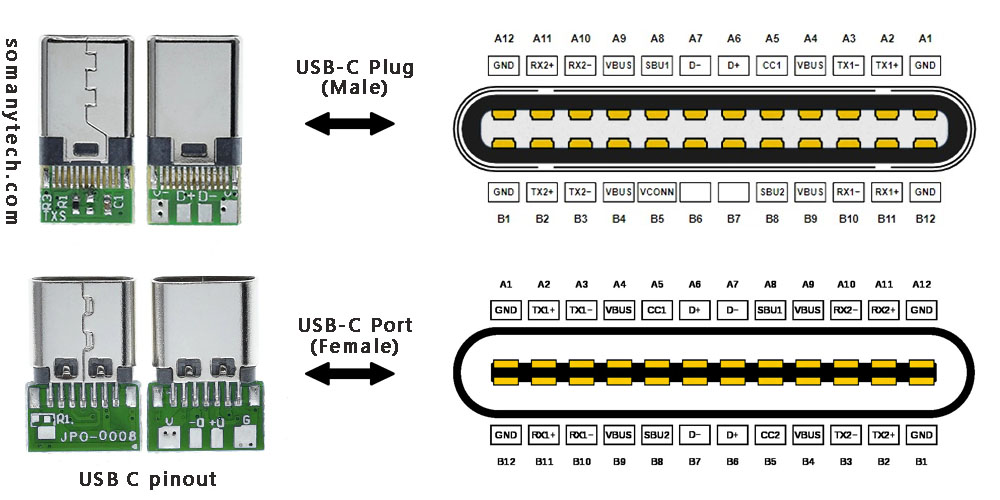
To the left in the above image are USB connectors with board as a USB 2.0 mode utilization, (D+, D-, VBUS, GND). Note that the USB 3.0 are fully functional cables connections are implemented with 8 or 10 connecting wires/bus.
The 24-pin double-sided connector offers a USB-C port that measures 8.4 x 2.6 x 6.65 mm. The 8.4 millimeters (~0.33 inches) is its width, the 2.6 millimeters (~0.10 inches) is its height, and the depth of 6.65 millimeters (~0.262 inches). The dimensions are for the internal side of a receptacle and outer side of a plug. And for more details refer to the datasheet provided by the manufacturer.
These connectors come in two forms: a male/ plug and a female/ receptacle. (see image above)
The Plugs are commonly found on cables and adapters, providing the means to connect devices. On the other hand, receptacles can be found on devices and adapters, providing a socket for the plug to be inserted into and for establishing connections.
Simplified USB C pinout with their functions are as follows:
The USB C pinout table, offering resources on the intricate details of USB-C connectors. By reading the table, you could understand various pins and their vital functions, enabling a comprehensive understanding of how USB-C devices and cables work together in conjunction.
With careful attention to detail, the table unveils an array of essential pins such as VBUS, GND, CC1, CC2, D+, D- and so on. Each pin have a distinct purpose, from power supply and communication channels to data transmission and more.
It’s a complex network of connectivity enclosing power delivery, audio, video, and alternate modes. As you explore USB protocols, you’ll gain a profound insight of the complex signals and connections within the USB-C ecosystem.
| Pin | Name | Description | Pin | Name |
|---|---|---|---|---|
| A1 | GND | DC ground (+0V) | B12 | GND |
| A2 | TX1+ | Super speed data transmit+ (host to device) | B11 | TX2+ |
| A3 | TX1- | Super speed data transmit- (device to host) | B10 | TX2- |
| A4 | VDD | DC power (+5V) | B9 | VDD |
| A5 | CC1 | Power delivery communication line | B8 | CC2 |
| A6 | D+ | Data transmit (host to device) | B7 | D+ |
| A7 | D- | Data transmit (device to host) | B6 | D- |
| A8 | SBU1 | Secondary bus | B5 | SBU2 |
| A9 | VDD | DC power (+5V) | B4 | VDD |
| A10 | RX2- | Super speed data receive- (device to host) | B3 | RX1- |
| A11 | RX2+ | Super speed data receive+ (host to device) | B2 | RX1+ |
| A12 | GND | DC ground (+0V) | B1 | GND |
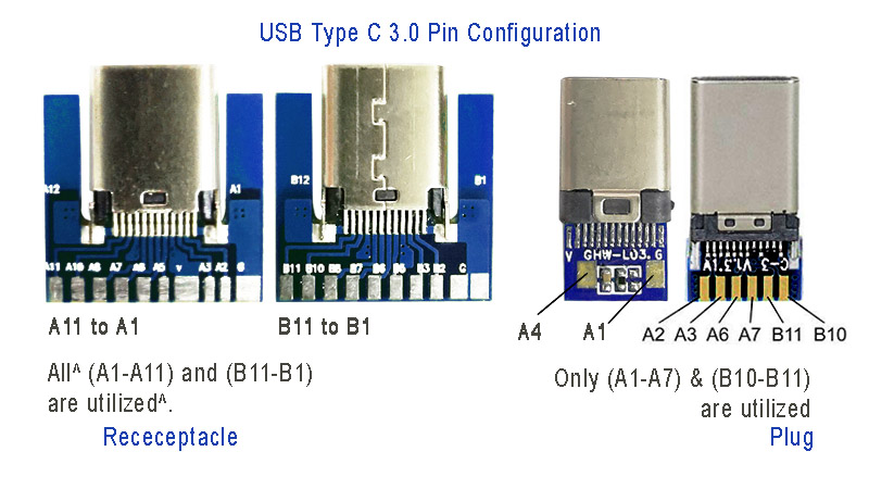
Below is an image showing USB type C 3.0 modules for high speed data communication:

Power: The A4, B4 and A9, B9 are connected to supply voltage. Also A1, B1 and A12, B12 are grounded. Thus, number of pins and wires to GND and VCC are reduced to 2 only.
SBU1, SUB2: These pins are called secondary bus. The A8, B8 are for side-band and are not utilized in USB communication and are reserved for future use. And therefore, the functional pins on each side remains to 9 each.
CC1 or CC2: These pins are used for Pin configuration detection, CC is used for USB-PD, i.e. USB power delivery communication to determine current control to the devices, for example charging current. Generally, CC is connected in series with a Resistor = 56k at port end. Thus, the total wires in the cable is found to be minimum 8 in numbers for functional high-speed USB C 3.0/ 3.1 type.
Also check micro USB pinout and how it is different from type C connectors.
Click here for helpful -> “wiring diagram for USB 3.0″ high speed data support and device charging.
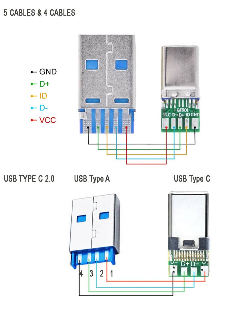
Below is an image showing USB type C 2.0 modules for older data transfer and charging:

The above image showing the schematic diagram USB type C 2.0 older standard version of mobile phone charging and data transfer cable. Note that there are two types available, one with ID pin and without ID pin. ID pin is sometimes connected to the ground or connected in series with some resistor.
These cable supports both power and data transfer, there are also power only charging cables that support only charging. Meaning, you cannot use them for tasks such as syncing devices, transferring files, or connecting peripherals. They are solely intended for charging purposes. They come with only two connecting wires inside, and they are thicker wires to offer lower resistance to the current flowing though them.
These are made to target devices like neckband/ earphone charging, for charging mobile-phones, USB powered LED lamps and other gadgets that have nothing to do with the data transfer. They are less expensive than the one with data sync capability.


