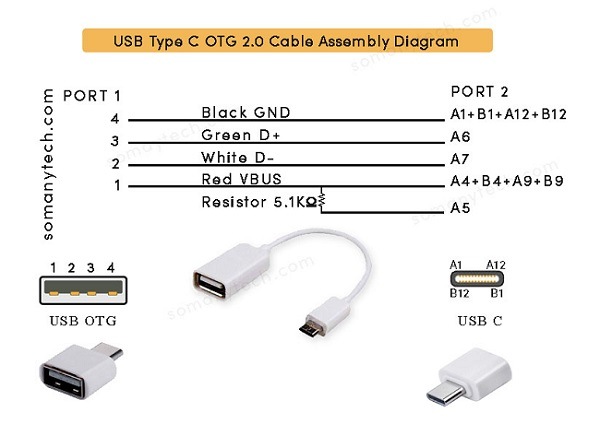
USB C OTG wiring diagram- Detail Internal connections
The USB C OTG wiring diagram below shows the “ USB type C to USB A female 2.0 type cable assembly”:
Before discussing the USB C OTG wiring diagram: Let’s lake a brief overview an OTG cable, or OTG connector.
An OTG C or On The Go adapter enable you to connect a full sized USB pen-drive or USB A cable to your phone through the Micro USB-C charging port.
They can be purchased separately from retailers, as they don’t come with a box in general when you purchase any device. The main purpose of USB-C OTG is a transfer of data with pen-drives as well as enable connectivity to peripherals like mouse and keyboard.
The USB Type-C cable, receptacle, and plug are designed to be more sturdy and user-friendly than existing USB cables namely Type-A and micro USB Type-B.
Let’s take an example, Type-A plugs connect only in one position to a Type-A receptacle (female port). The Type-C connector, however, lets you connect the device downside up or upside down. By making this simple change, USB devices can be inserted correctly into USB ports without frustration.
USB C 2.0 OTG (OTG) product is a portable device, that can function either as a USB host or a USB peripheral. All USB 2.0/ 3.0 OTG products are required to use a micro-B/micro-C receptacle.
Fig. shows the receptacle pin assignment for supporting a semi-featured Type-C cable. A full-featured cable supports both USB 2.0 and USB 3.1 (higher data speed). Below is the USB Type C 2.0 OTG wiring connection USB A to USB C:

Also check, USB type C Wiring Diagram for Charging Cable
Table 1 shows the pin-out for both receptacle and plug of USB OTG.
| USB A receptacle | USB C port | Wire code | Description | Symbol |
|---|---|---|---|---|
| 1 | A4, B4, A9, B9 | Red | +5V (dc power) | VCC/ VBUS |
| 2 | A7 | White | Data- (data from device to host) | D- |
| 3 | A6 | Green | Data+ (data from host to device) | D+ |
| 4 | A1, B1, A12, B12 | Black | 0V (dc ground) | GND |
| NC | A5* | - | Configuration Channel 1 (VBUS through resistance Rp =5.1kΩ) | CC1 |
Description:
The OTG device functions as a USB peripheral. When acting as a USB peripheral, the portable USB 2.0 OTG product observe VBUS signal to determine whether it is connected to a USB host or external mobile charger.
- The Pin no A1, A12, B1, B12, of USB C port is connected to the Pin no.4 USB type A receptacle. This pin is named as the ground (GND) through that pin ground signal is established.
- The Pin no A4, A9, B4, B9, of USB C male is connected to Pin no.1 from USB type A receptacle male. This pin is the power supply (5+ volt/ VBUS) through that pin the power is supplied to the device and it can be host or peripherals.
- The Pin no. A6 of the C- port is connected to Pin no.3 from USB type A receptacle.
Also, the Pin no. A7 of micro USB C is connected to the Pin no.2 from USB type A female.Pin no. 2/A7 (D-) and pin no. 3/A6 (D+) both as a pair are used as a differential data pin in each port. - The colors code of wire used in the USB C OTG cable are Red, White, Green, Grey/Black, corresponding to pin 1, 2, 3 & 4.Check USB C color code of internal cable here!!
- (CC pin) A5 at USB port C side is connected to Vbus pin through a resistor of 5.1k ohm.
Some applications of OTG cable are mention below, other than techie, most of the general users don’t know what is the use of OTG adaptors:
- Connecting keyboards and mouse to the mobile phones to enhance usability of mobile apps.
- Accessing/ copying/ deleting the USB pen drives data and external hard drives.
- Transfer photos directly from a PC or compatible camera on to the phone.
- Connecting smartphone directly to the devices like photo printers/ 3D printers.


