USB Type C wiring diagram- Charging Cable diagram
USB Type-C is a new replacement for the earlier micro USB connector system. Almost all the new budget smartphones that are being released every few weeks come with micro USB C due to their gaining popularity across the smartphone and gadgets section. The major advantage of USB C over the previous micro USB is its port compatibility on either sides of device i.e it can be inserted upside down or vice versa without any technical disadvantage.
In this article, we will discuss the most important features of the USB-C other than its ability to flip for which it is most popular. The following information will be helpful to electronics hobbyists and to anyone who is trying to learn the different types of Universal Serial Bus or for any sort of USB C wiring repair work.
Before getting into the USB C wiring diagram, you can check the detail on the USB C pinout and explanation of what each pin does. If you want to know the usb which is used to be one of the most commonly used usb standards then check the older micro USB pin-out and wiring diagram.
USB Type C wiring diagram PD (Power Delivery) & USB 2.0 Data
There can be three possible ways of USB C wiring:
USB C charger cable wiring diagram:
The first one is USB type C to USB A male that comes with a mobile phone charger in the box. This cable is capable of transferring data from/ to personal computers as well as charging the smartphone. In this, there you could find two versions viz., USB 2.0 & USB 3.0. Out of which USB 3.o has more connecting wires and supports high data transferring speed than that of USB 2.0.
USB C OTG wiring diagram:
The second one is USB type C to USB A female which is also known as USB C OTG cable. USB OTG cable comes in handy when transferring files and photos from a USB pen drive to a mobile phone or vice versa without connecting either a mobile phone or external storage device to a Laptop or PC. Also, it supports pointing device like mouse and full external keyboard for typing. USB C OTG also comes with this USB2.0 and USB3.0 formats.
USB C to USB C wiring diagram: These cables support high-speed data transfer up to 10Gbps, it is incorporated with the USB 3.1 version. It has the USB C port on both the end, which makes the connection very easy as you won’t need to use your brain to check port orientation on either side.
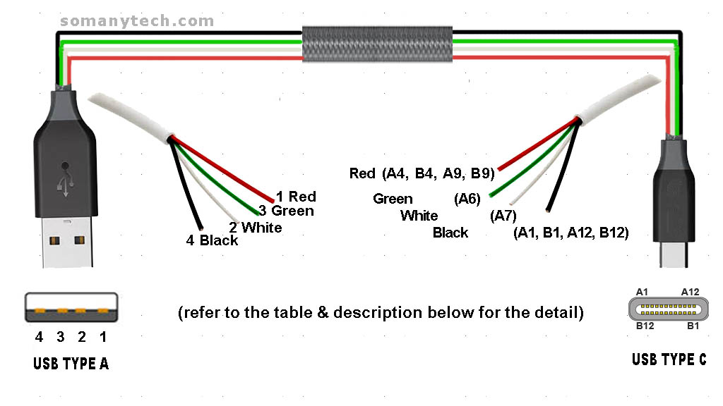
USB type C wiring diagram with male USB 2.0 type A:

The cable shown in above image is typically found used in mobile chargers for charging mobile devices and as a USB data cable to connect mobile devices for transferring files and images between personal computers and phones.
Under the latest development they are called Power Delivery (PD) cable. PD cables are only designed to charger the mobile and laptop devices. Only PD supported cables doesn’t support data transfer. But most of the cables supports both power delivery and USB 2.0 470 Mbps data transfer rate. Small cables that comes with bluetooth neckband/ headphones are made for charging only that too for lower current application, and thus they are not reliable for fast mobile phone charging.
The table shows the connection between pin numbers on both the end and their function with their character symbol:
| Pin no. at USB A | Pin no. at USB C | Wire code | Description | Symbol |
|---|---|---|---|---|
| 1 | A4, B4, A9, B9 | Red | +5V (dc power) | VCC/ VBUS |
| 2 | A7 | White | Data- (data from device to host) | D- |
| 3 | A6 | Green | Data+ (data from host to device) | D+ |
| 4 | A1, B1, A12, B12 | Black | 0V (dc ground) | GND |
| NC | A5* | - | Configuration Channel 1 (VBUS through resistance Rp =5.6kΩ) | CC1 |
- According to the USB standard power supply is +5V. (but note that the capacity of the maximum output current supply is different for different USB versions).
- Pin no.1 from USB type A male is connected to the Pin no A4, A9, B4, B9, of micro USB C. This pin is named, the power supply (+VDD/ VBUS) through that pin the power is supplied to the device or any equipment which is also an indicator of handshake signal, that convey the system that “the device is connected”.
- Pin no.4 from USB type A male is connected to the Pin no A1, A12, B1, B12, of micro USB C. This pin named the ground supply (GND) through that pin ground signal is connected.
- Pin no.3 from USB type A male is connected to the Pin no. A6 of micro USB C.
Pin no.2 from USB type A male is connected to the Pin no. A7 of micro USB C. Both Pin no. 2/A7 (D-) and pin no. 3/A6 (D+) are used as a differential data pin in each port. Data is sent from and received from the differential data pins in a specific format, called USB protocol. - Whereas, the color code for the wire used in the USB C cable is Red, White, Green, Grey/Black for pin numbers 1, 2, 3 & 4 respectively.
- Note: In some cables, it could be found that Pin no. A5 is not connected to anything at the USB C side. As, low-end manufacturers avoid it to reduce time and money to some extent. But good quality expensive cable has A5 connected.
It is suggested to connect A5 at USB port C side according to recommendations.
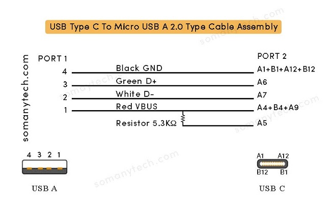
The USB C wiring diagram below shows the “ USB type C to micro USB 2.0 type cable assembly” diagram:
- USB charging cable and USB OTG cable have the same cable assembly diagram apart from their ports. (USB 2.0 type A male/ female have same wiring only difference is port).
- This means, out of two ends, one end is common viz, USB C PORT, and another end could be either a USB A male or USB A female. This serves two different purposes USB charging/data cable and USB OTG cable respectively.

- *Important: Note that pin A5 /(CC) shall be connected in series with resistor Rp= 5.1kΩ/ 5.3kΩ/ 5.6kΩ with the +5v supply (VBUS). The value of Rp determines the current capability of the cable/ device for which it is designed.
- For a good quality USB cable, it is recommended to have internal shielding on all wires inside, with 360-degree shield termination on both ends.
- This shielding is often named SHELL/ SHIELD/ BRAID. They are conducting in nature and grounded at ends.
- The purpose of shielding is to prevent unwanted RF interference and noise signals.
USB C to USB A 3.0/3.1/3.2 type cable wiring diagram:
Click here to check USB C 3 cable pinout and wiring


