IRFZ44N, Datasheet PDF, Circuits, Pinout, Equivalent, Alternatives
In high-current switching scenarios, the IRFZ44N MOSFET is a well-regarded choice. Such powerful transistors play crucial roles in various applications, including device and motor control. The IRF3205 is known for its durability and efficiency, making it a preferred option for tasks requiring very high speed switching and handling high power. Thus, comprehending the features and capabilities of this transistor is significant.
In this article, we’ll explore the IRFZ44N, including its pinout, equivalent components, practical uses, features, and how and where to use this high-current N-channel MOSFET.

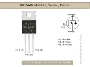
The IRFZ44N, made by International Rectifier, is easily recognized by its part number prefix. It boasts low on-resistance, fast switching, and efficient HEXFET power MOSFET design, making it suitable for various commercial and industrial applications with power dissipation needs of up to around 50 watts, preferred TO-220 package.
Main Features:
Maximum Rated voltage across Drain & Source → Vdss= upto 55V
Maximum operating current → Id = upto 49 Amps
Gate voltage → VGS(th) = 2V – 4V and above
Resistance → R(DS)(on)= 17.50 mΩ
Primary function → High current high speed switching.
Parameter overview:
The IRFZ44N MOSFET is designed for high-power applications, with the ability to handle a drain-to-source voltage of up to 55 volts. Additionally, it can be triggered with a minimal gate voltage ranging from 2 to 4 volts and above it could be used, making it suitable for low-voltage control. Its maximum operating current of 49 amps is achieved thanks to its exceptionally low drain-to-source resistance of 17.5 milli-Ohms.
| Package | TO-220 | Transistor |
|---|---|---|
| Component | N-Channel | MOSFET |
| Drain to Source Voltage | 55v | Max. |
| Continues Drain Current | 49A | Max. |
| Voltage Required to Conduct | 2V to 4V | Min. (threshold voltage) |
| Drain Source Resistance | 17.5mΩ | On state |
| Pulsed Drain Current | 160A | Max. |
| Power Dissipation | 94W | Max. |
| Switching time | @ Vdd=28V, Id=25A, Vgs=10V | |
| Rise time | 60nS | Typ. |
| Turn-On delay | 12nS | Typ. |
| Turn-Off delay | 44nS | Typ. |
| Fall time | 45nS | Typ. |
| Internal Inductance & Capacitance | - | Check Datasheet below |
| Operating temperature | -55 to +170 | Degree Centigrade |
While these figures represent the absolute maximum ratings, it’s advisable to operate this transistor at around 80% of these limits to ensure safe and reliable performance.
For detail characteristic like Vgs vs Id, Vds vs Ids, check and refer to the IRF3205 Datasheet below.

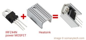
Make sure the MOSFET is connected properly to a heat sink when operated with a high current application over 2 Amps to ensure proper operation and to increase MOSFET life.
How to test IRFZ44N MOSFET if it is good or faulty?
(Removing the mosfet from the PCB improves the accuracy of the test)
- Check Gate Source: In Diode Test mode, connect the positive probe to Gate (G) and the negative probe to Source (S). A voltage drop of around 0.5-0.7 volts indicates a good MOSFET.
- Check Drain Source: Set the multimeter to M-Ohms (Resistance) mode and place the probes on Drain (D) and Source (S). A high resistance reading or “OL” (out of range) suggests a good MOSFET.
If the results don’t meet the specified criteria for either test, the MOSFET is likely faulty; otherwise, it is considered in good condition.
For more details on how to test MOSFET click here! (link)
Alternatives & Replacement:
IRFZ44N is very popular and widely available, but if you don’t find it available near you, then its consider alternatives.
The 1st and nearest IRFZ44N alternative is IRF3205, as its specifications are almost same & adding higher current handling capacity. Other alternatives are IRF1405, IRF1407, IRF540N, 2N7000, FDV301N IRF3305, IRFZ44N, IRFB3077, IRFB4110.
Check this 8205A dual Mosfet IC datasheet which is popular in battery protection circuit.
IRF3205 Vs IRFZ44N & Differences Comparison:
It seems like IRF3205 is optimized version of IRFZ44N, IRF3205 is optimized for higher current capability and lower channel resistance as compared to IRFZ44N. In this process of optimization, they have to trade off between operating current and switching time.
Thus, you can observe that the switching time of IRF3205 is lower; and the Maximum Drain Source current is higher (at 110A) than that of IRFZ44N (at 49A). Although the switching time has marginal difference of few nanoseconds, it has lesser to negligible effect on high current load switching.
| MOSFET | IRF3205 | IRFZ44N | (only main difference are:) |
|---|---|---|---|
| R(DS)(on) | 8.0mΩ | 17.5mΩ | Drain Source Resistance |
| Id (max operating current) | 110A | 49A | Continues Drain Source Current |
| Switching time | Lower | Higher | Check datasheet below for more |
All the parameters as technically similar, so as to use them as an alternative/ replacement other than that of Maximum Load Current/ Drain Source Current.
Application/ Uses:
Automation devices for controlling loads in IoT application, Boost and buck converters, Solar inverters, DC motor speed control, Static Relay driver, SMPS (switch mode power supply), power inverters, embedded system, high-speed switching.
IRFZ44N Switch Circuit diagram for Arduino and General application:
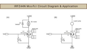
Connecting an Arduino to the IRFZ44N is a simple process, which makes it adaptable for various applications, including IoT and as a relay driver for high-current loads like DC motors and DC Load. The following circuit illustrates how to connect a DC motor and load to the IRFZ44N MOSFET. Ensure proper pin connections to avoid short circuits, particularly for the drain and source.

Although not mandatory, but it’s recommended to include a Gate-Source resistor for circuit optimization. This versatility allowed due to the MOSFET’s ability to handle a wide range of input voltage and current, as indicated in the datasheet for this transistor. (refer the datasheet of this transistor).
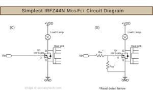
For design purposes, you can consider using R(IN) with values of 100 Ohms or 220 Ohms and R(GS) with values of 10K or 100K-Ohm.

In the circuit diagram presented above, option (C) represents the simplest configuration for utilizing the IRF3205 to control various types of loads. Option (A) incorporates a fly-back diode in parallel to prevent reverse polarity voltage spikes from the DC motor, which can occur due to its inductive nature of a DC motor.
IRFZ44N Datasheet PDF:
Download IRFZ44N datasheet PDF here. (link)


