
3 Best ways to test a relay? in 5 minute
Depending on the type of relay we will discuss how to test a relay using different methods.
First of all, identify the relay you want to test with the help of the image given below. From this image check the similar match relay. (Scroll down for explanatory video)
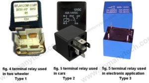
The first is starter relay in a bike, 2nd image is a 5 pin relay used in cars also called as starter relay, 3rd is a relay which is used in electronic circuits, we will learn how to test a relay of each type.
General and most common faults found in starter relay are at:
i) Coil: ( burnt coil, broken connection)
ii) Movable contact: (lost its flexibility, carbon covered/rusty contact due to sparks)
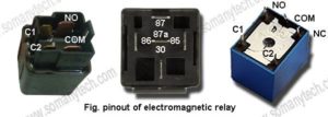
Pinout diagram with the notation:
NC: Normally closed
NO: Normally opened
COM: Common
C1/C2: Power supply to the coil
(just keep in mind that types of relay differ only on the basis of the number of terminals but the actual principle of working is same i.e principle of electromagnetism). If you have identified the type of relay with the help of the above image, then just follow one of the following methods.
Check how to test a relay with multimeter in different ways:
For type 1 and type 3 relay
The first method is by using a multimeter, set the mode of multimeter in the Continuity mode.
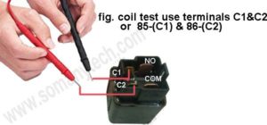
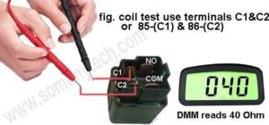
Step1: Connect the two probe of multimeter to the coil terminals ( C1 & C2) as shown
if it buzzers then your Electromagnetic coil is OK.
If it does not buzzer this means that your coil is Faulty.
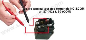
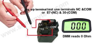
Step2: Once it buzzers, you need to check the output terminals of the relay. Connect your multimeter probe to the terminal contact (NO & COM) if it doesn’t buzzer this means that contact terminal is Ok, otherwise, it is Faulty.
or
Connect your multimeter probe to the terminal contact (NC & COM) if it Buzzers means that contact terminal is Ok, otherwise, it is Faulty
How to test a relay for type 2:
Step1: The two probe of multimeter and the coil terminals 85-(C1) & 86-(C2) are to be connected as shown. If the buzzer ring then your exciter coil is Ok (check above images).
Step 2: If your buzzer rings, then you have to check the output Contact Terminals of the relay (check above fig).
(NO terminals) Connect your digital multimeter probe to the terminal (87 & 30), if the Buzzer does not ring this means that the contact terminal is working fine, otherwise, it is faulty.
or
(NC terminals) Connect your multimeter probe to the terminals (87a & 30), if the Buzzer sounds, means relay movable contact is fine, otherwise it is faulty.
How to test a relay with a multimeter:
(resistance mode)
(common for all type)
At first, Set the mode of multimeter to the Resistor mode. Then connect the Red and Black probe of the multimeter to the coil of the relay:
Observations:
- The value of resistance for or type 1 relay should be between 30Ω to 150Ω.
- For type 2 relay, the resistance value should be between 300Ω to 900Ω.
- And for the type 3 relay, the resistance value should be between 20Ω to 450Ω.
Along with it, NO and COM contacts must show 0 Ω, which means it is open-circuited when no input is given.
[ important: You must refer to the datasheet of this devices before concluding to a result. As this value of resistance varies with different types of relays available in the market]
How to test a relay without a multimeter?
Apply a 12 volt/9 volt/5-volt power supply to the coil (apply voltage according to the rating printed on it) and you will hear “crisp-click” sound, this indicates that your movable contact is working fine and thus the relay coil is in good condition. (This method only checks weather coil is working or not)
Bonus tips:
- If your start relay is not working or working occasionally then consider replacing it with a new one this is because your relay’s movable contact might get covered with carbon.
- Our team has observed that some motorbikes/ mopeds which are available in the market have starter relay problem more often Yamaha’s starter relay is at top.
Relay a device that drives high power circuit with the help of the low power circuit, a relay is necessary for the circuit where we have a small current it and need to drive high current applications. It is very commonly used in motorbikes and cars to drive the ignition.
Home Automation Systems installs a large number of relays to control various home appliances remotely and through chips.
The symbol of an electrical relay is as shown:
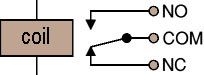 When the current through electromagnetic coil flows it acts as a temporary magnet and attracts the movable coil which changes the circuit arrangement and this change is utilized to work as required.
Therefore when we supply power to a coil it closes the circuit and If we retract the power to the coil, then the circuit loses its connection with the terminal. Therefore, the circuit is opened.
In conclusion, the relay is an “electromagnetic switch” for controlling high current devices with the low current circuit.
