

Low Pass Filter – Design, Schematic, advanced guide
What is a low pass filter?
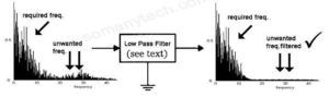
Before understanding the low pass filter let’s look at what is a filter. Have you ever heard of strainer? if yes then you must know the use of strainer, it is used for straining solids from liquids, or for separating coarser particles from finer particles, in short, the strainer is used to filter out the unwanted impurities in the solution or liquid and allow only what is required.
Similarly, filters are the device or circuits which are used where only the required range or a frequency is required.
The frequency range can be all frequency less than particular frequency, the difference between two predetermined frequency, or frequencies above particular frequency.
The main categories of the filters are high pass filter low pass filter Bandpass filter, notch filter/band-reject filter.
Definition: Low pass filter
Low pass filter (LPF) is a filter that allows signals with a frequency lower than a particular frequency (that particular frequency is called cutoff frequency).
And does not allow the signals of frequencies higher than the cutoff frequency.
In other words:
- LPF is a circuit that is designed to reject unwanted higher frequency of electromagnetic signal, audio signals, electrical signals and accepts only those signal which is required in the applicational circuits.
- A low pass filter is a circuit that attenuates all the signal components above cutoff frequency to a considerable level.
- Technically, any filter can be classified as the ideal filter and practical filter the figure below showing the ideal and practical response of low pass filter:
Ideal LPF can be defined as the filter having the ideal response of input versus output frequencies, i.e, it must have zero attenuation for all pass vacancy and infinite attenuation for or blocked frequencies as shown in the figure.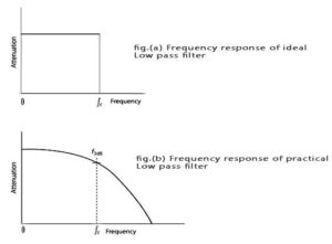
Idea LPF shows a flat response. But practically it is not possible and we get a slightly curved response, this is due to non-ideal components we use in making LPF.
Types of low pass filters:
a) Active low pass filter
b) Passive low pass filter
Active low pass filter:
It is a low pass filter that uses the external power supply to give required output frequencies with the specific Gain.
This is because the filter circuit itself consumes some power which is not desirable for the circuits which use very low input power and therefore unable to process the input signals.
Generally, active low pass filter is used in “Amplifier with equalizer” and Critical radio frequency circuit designs.
Passive low pass filter:
It is LPF which does not use any external power supply and just filters out the higher frequency to give the lower frequencies.
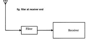
It is used in audio circuits, power supply circuits to eliminate the noise, and radio circuits to select lower frequencies and avoid high-frequency noise in the receiver end.
let’s discuss passive low pass filter in detail:
A passive low pass filter can be implemented in multiple ways using the given schematic. A few of them are RC filter, LC filter, RL filter, and some topology includes, Butterworth filter, Chebyshev filter, π filter, T filter, and so on.
Butterworth filter, Chebyshev filter, π filter, T filter, k filter, etc come under modern filter design. Detail analysis of these filters will be published in the next post.
In this post, we will be discussing the traditional and basic ways of implementing the low pass filter.
Terminology Used :
1) Pass band frequency: Frequencies that are allowed through the filter without/low attenuation are called passband frequencies.
2) Stop band frequency: Frequencies that are completely blocked, face high attenuation are called stopband frequencies.
3) Bandwidth: It is the range of particular frequencies.
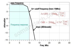
4)Cutoff frequency (higher cutoff frequency/ lower cutoff frequency): The frequency at which the filter offers half of the power loss which is equal to 3db loss which is equal to (0.707 Vi).
RC low pass filter:
In the RC low pass filter, we use two components namely Resistor and Capacitor.
This is the most used low pass filter schematic for Audio proposes and Rectifier filter purposes.
The reason behind this is very simple as they are available at low cost and therefore the first choice for mass production.
The figure showing the schematic of the RC low pass filter:
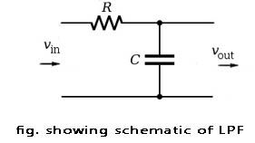
The basic circuit of the RC low pass filter consisting of the resistor in series and capacitor in parallel with the load.
(not the position of the capacitor because this is the component that decides whether the filter is low pass or high pass)
Working:
So how this circuit blocks higher frequencies?
This circuit used the capacitor’s property of Reactance Xc which acts as a short circuit for higher frequencies and therefore higher frequency cannot travel to the Load.
On the contrary it blocks the low-frequency signals through it, which in results pass through the load.
Another way to understand this is through learning the charging and discharging time of the capacitor which is responsible for behavior two different frequencies.
The combination of R and C creates a charging and discharging effect on the capacitor called as its Time Constant ( τ ) of the circuit.
τ = RC seconds
For lower frequencies, there is sufficient time for the capacitor to charge at the same voltage that of input and results in an open circuit.
For higher frequencies, there is less amount of time for the capacitor to charge Before the negative cycle come and results in short circuit.
What determines the passing frequency and blocking frequency?
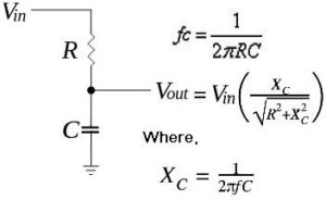
fc=1/(2 π R C)
The tau ( τ ), τ= RC ,is the time constant is dependent on the cut-off frequency ƒc as above.
Here frequencies lower than ‘fc’ are passed and higher than that is blocked see example below.
(check figure for all formulae)
RL low pass filter
RL LPF uses of resistor and inductor in the same configuration as that of RC LPF.
Generally, RL low pass filter is avoided for implementation as a filter because of large size and wt. of the inductor (particularly for higher values of components), non-linear frequency response over the change in temperature, also quite complex to implement.
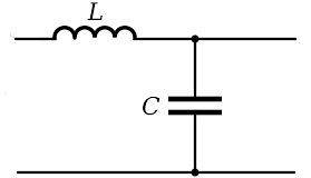
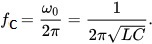
LC low pass filter
LC-LPF Is made up of inductor and capacitor, this is another most used LPF. The reason behind this it has simplicity and accuracy of frequency response. a very e sharp cutoff frequency is achievable using an LC filter.
The radio circuit the receivers, the transmitters, the modulators use the LC filters. Or you can say that any RF circuit which is required to inhibit low power loss and better stability uses LC filters.
The formula and schematic for the LC low pass filter:
Let’s analyze a low pass filter with a practical example :
Q. Design a low pass filter having cutoff frequency ‘fc‘ = 75MHz and Vin = 5 volts using RC filter?
Solution: given -> f = 75Mhz.
R = 100 Ω(assumed)——-<assume either the value of R or C>
C = (to find)
Formula, fc = 1/(2 π R C)
Putting the values we get , C = 21.2 pF. Hence the design
Further analysis,
Find Xc= ? —–[using formula Xc= 1/(2π f C) ]
Therefore, Xc1 = 100.14 (75Mhz) ;.
Xc2 = 8.23 (900Mhz)
Vout = Vin[Xc/sqrt(R²+Xc²)]
putting the value
We get, Vout = 3.54 Volts for freq. 75 Mhz—-(i)
Vout = 0.41 Volts for freq. 900Mhz—-(ii)
From result i), ii) we observed that for ‘designed the frequency’ we get is almost zero loss than that of ‘out of designed freq’ range. Hence LPF designed according to requirement.
There are other ways too for implementing it, which we will discuss in the next post.
Improving the frequency response:
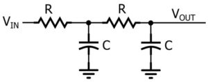
Improving frequency response means steps towards achieving to near ideal frequency response curve. We can implement this using increasing the number of orders.
Here order means the number of stages of the same circuit. if two to RC filter is used in series there it is second-order filter. if we use three RC filters side by side there it is a third-order filter.
And this goes on, but there is a certain limitation to use the higher-order filter. Those imitations are attenuation(insertion loss) of passband frequencies, noise insertion, etc
By increasing the order of the filter, the dB gain roll-off decreases and thus gives a sharp response.
The figure below shows a second-order filter (1st order+ 1st order):
Applications of LPF:
1) In receiving-end of radio receiver television receiver etc specifically in the superheterodyne receivers.
2) In power electronics to filter out high-frequency noises.
3) In demodulation circuits to recover the original signals eg. FM/AM receiver.
4) R-C type LPF is used as an integrator.
5) In phase detection in the phase-locked loop.
Modern filter design:
Why there is a need for modern filter design?
Modern filter design is gaining popularity within the circuit design engineer due to better frequency response and stability. But the disadvantage of the modern filter is its complexity.
Even though these designs are complex it is preferred among RF IC designers.
Below are the most popular topologies:
a) Butterworth filter
b) Chebychev filter
c) Bessel filter
d) K-filter, etc