7 Simple Power Bank circuits using TP4056 & 18650 battery
This article will take you through all the aspects of a power bank circuit at home, with an in-depth steps to building power bank along with different modules, circuit board, connection diagram, and external case to use with it.
Nowadays it has become very impossible not to have a portable charger, alternate power source to recharge your smart phone as becoming very hard to maintain a phone’s battery for a day without charging due to the heavy usage of smart phones in day-to-day life. The best way is to carry a mobile charging source i.e a power bank.
If your old power bank got damage or not working then this article could be helpful to you in repairing your old power bank at a very low cost even without the need to buy a new one. The best way is to simply DIY yourself a new one or repair the non-working power bank.
Also check Simplest 18650 Battery Charger circuit with auto cutoff DIY
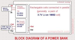
Block diagram of a typical power bank circuit:
Block diagram of a power bank primarily consist of three main functions as shown in the above image: A charge controller, 5v boost converter, Li-ion battery.
a) Battery charge controller circuit:
The function of the battery charge controller circuit is to control the state of charge of any battery according to its capacity and rated voltage. Other than this, it also helps battery against overcharge.
Here, a lithium-ion charger module which is based on IC TP4056/ TP4054 is used and a micro USB port to charge the battery is present.
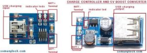
The battery charge controller module TP4056 in the image is designed keeping in mind the highly critical li-ion batteries and reduced manufacturing time and cost by using SMD components.
b) A 5-volt boost converter circuit:
The function of the 5-volt DC-DC boost converter circuit is to convert the lower voltage of a battery to 5v regulated DC. Here, it converts 3-3.7 v DC obtained from LI-ion batteries (std. 3.7 volt is rated) to steady 5volts so that our mobile charges at standard voltage normally.
A DC-DC boost converter comes with a female USB port to connect a USB cable from our mobile phone to it. The boost converter module works on the principle of (PFM) Pulse Frequency Modulation.
Check this interesting video below on working of power bank:
c) Rechargeable lithium-ion batteries:
Everybody knows the function of batteries, the only thing to consider is to use rechargeable batteries aiming at re-usability. The battery pack in power bank is a combination of 3.7 volt li cells connected in parallel.
The 18650 cells are the most commonly used Li-ion cells in the market these days. Some power bank brands use flat li-ion cells to make it thin and compact.
You can read the 18650 battery specification here.
d) Battery level display unit (optional):
The display unit may be or may not be present in a power bank as it adds the extra cost to the product company prefer to eliminate it in low-end products. The battery level display unit has two functions, first is to show the state of charge in percentage (%) and second is to indicate charging of both mobile phone and power bank.
Working: The power bank is a simple power backup device for your iPhone which is portable/ handy instantly to charge a phone when the battery is low.
The charge controller charges the battery to its appropriate level and protects it from damage caused due to overcharging. Our mobile phone’s battery needs 5volt dc at 1 A or 2 A but cells inside the p-bank have the maximum output voltage of 3.7 volts. Thus a boost converter boosts up the level to 5Volts which is required to charge a phone. The modules come with an input port (micro USB) for charger and output ports (USB female) for mobile charging.
Watch how power bank circuits and controllers work at the end of this post.
Power Bank circuit using module TP-4056 and a 5v boost converter:
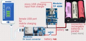
In this circuit, a total of 3 lithium-ion cells are used. All batteries are connected in parallel with each other connection to increase backup of a power bank.
As we know that in parallel connection of batteries voltage remains the same but current capacity is increased. So for increasing the current all batteries must be connected in a parallel configuration.
Connection:
Assemble all li-ion cells 18560 in a parallel configuration and put it into a casing or just tape it. Means solder positive terminal of one cell to the positive terminal of other cell and negative terminal to the negative terminal. Now we have two wires one is red positive and black negative wire. Connect the black wire to negative of 5v boost converter module and to controller module TP4056. Similarly, connect positive terminal from battery to positive terminal of both the modules.
Keep in mind, the marking on the module + and – accordingly connect wires. You can put all these components in an assembly case. Its done DIY power bank is ready to use, make sure you charge it completely before using it for 1st time.
18650 battery charger circuit (how to charge 18650 battery)
Power Bank circuit using dual USB output port module:
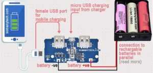
In this circuit we will use all in one module, it comes with dual USB 5volt 1A/ 2A rating. Various modules for this function from the different manufacturers are available with slight change in specification.
Connection:
Assemble all 18560 rechargeable cells in a parallel configuration as mentioned above. Means solder +ve terminal of one cell to +ive terminal of other cell and a negative terminal of one cell to negative terminal of other. Connect the black wire from battery to negative terminal of this dual USB out power bank module. Similarly, connect +ive terminal from battery to +ive terminal these modules.
There are markings on the module as + and – symbols make sure you follow the circuit diagram
Power Bank circuit using a single USB output port compact module:
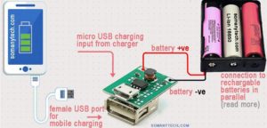
In this circuit we will use a compact module, it comes with a USB 5volt 1A rating. It is used where only one USB output is sufficient for use, also saves space as it is very compact. The major advantage for this module is that it restricts simultaneous charging and discharging of power bank that prevents its board from damage.
Connection:
Assemble all li-ion cells 18560 in a parallel mode, just solder positive terminal all cell to red wire and negative terminal of all cells to the black wire. These two wires, one is red positive and black negative wire are connected to the positive and negative of the charger controller module respectively. The marking on the module may be B+ and B- note that while connecting.
Using this circuit you can repair your power bank, just remove the batteries from an old p-bank and use it with third-party module. (depends on what part of old p-bank is faulty)
Solar power Bank circuit using TP 4056 and a 5v boost converter module:
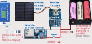
What if you don’t have to recharge your power bank more frequently? Here is a twist, make is solar powered power bank. An extra component is needed i.e a solar panel module of 5volt 500mA/ 1000mA. Buy it and follow the connection diagram below, go through the power bank internal circuit.
Connection:
As we know that all li-ion cells 18560 must in parallel connection to use it with the modules to utilize battery capacity. Take any two-color wire to join positive terminal with one wire and -I’ve with others wore and mark it down for further wiring.
On controller module TP4056 circuit board locates +N and -N terminal. On that terminal connect positive terminal from battery to +N terminal of a module and -ve terminal from battery to -N terminal on the circuit board. Make sure the symbol on the module + and – , never interconnect wires because it will burn the circuit board. Remaining wiring is easy as shown in the image. Assemble it smartly to look good and voila! it’s done. Now use your power-bank whenever required and feed it sunlight to recharge it.


