IRF4905, Datasheet PDF, Specification, Pinout, Circuits, Alternatives
In need of high-current switching application, the IRF4905 MOSFET is one of the preferred choice. The IRF4905 stands out for its reliability and efficiency, making it the preferred selection for applications requiring rapid switching speeds and the power control system.
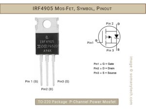
In this article, we have discussed IRF4905, check its pinout, equivalent, practical applications, distinctive features, as well as instruction on when and where to employ this high-current P-channel MOSFET.

Main Features:
Maximum Rated voltage across Drain & Source → Vdss= -55V
Maximum operating current → Id = upto -74 Amps
Gate voltage → VGS(th) = -2V to -4V and lower
Resistance → R(DS)(on)= 20.0 mΩ or 0.02 Ω
Primary function → High current high speed switching.
Parameter overview:
The IRF4905 MOSFET is designed for high-current application, having a remarkable -55 Volt drain-to-source voltage limit. Its gate trigger voltage, starting from -2 volts up to -20V, making it suited to a low-voltage switching control applications as well. As a result of its exceptionally low drain-to-source resistance, the device has an operating current capacity of -79 Amp. With industry standard footprints, this device is available in surface mount and through-hole packages for ease of design.
Check! this popular n channel MOSFET IRF3205
All Features:
| Package | TO-220, | Transistor |
|---|---|---|
| Nature | P-Channel | MOSFET |
| Drain to Source Voltage | -55v | Min. |
| Continues Drain Current | -74A | Max. |
| Voltage Required to Conduct | -2V to -4V | Min. (threshold voltage) |
| Drain Source Resistance | 20.0Ω | On state |
| Pulsed Drain Current | -260A | Max. |
| Power Dissipation | 200W | Max. |
| Switching time | @ Vdd=-28V, Id=-38A, Vgs=-10V | |
| Rise time | 99nS | Typ. |
| Turn-On delay | 18nS | Typ. |
| Turn-Off delay | 61nS | Typ. |
| Fall time | 96nS | Typ. |
| Internal Inductance & Capacitance | - | Check Datasheet below |
| Operating temperature | -55 to +175 | Degree Centigrade |
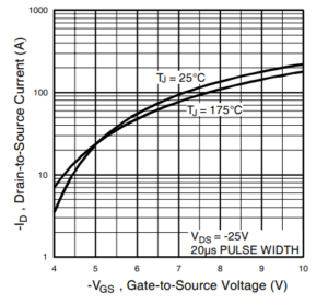
The below plot showing Typical Transfer Characteristics of MosFet:
-Id (Vs) -Vgs, @ Vds=-25V, Pulsed Drain current @20µs with junction temperature maintained at 25°C and 175°C. It can be observed that this MOSFET can be used at as low as negative 2V-4V for lower current application of up to 5Amp. But for higher Load
Current you need to drive the gate with an appropriate voltage (-Vgs) ensuring guaranteed optimal switching performance.

For detail characteristic like Temp. vs Id, Vds vs Ids, check and refer to the IRF3205 Datasheet below.
When working with the MOSFET IRF4905 circuit, it’s essential to follow recommended practices, including:
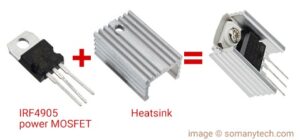
Review the datasheet for detailed electrical characteristics and guidelines, especially when implementing P-channel applications. And ensure proper heat sinking to dissipate any generated heat effectively.

Application/ Uses:
High ruggedness and current capability make it an industry-standard choice. Widely available through distribution partners, ideal for low-frequency applications <100kHz and drop-in replacements due to standard pinout.
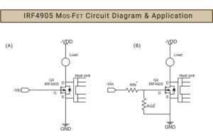
Some of the application of IRF4905 are: DC motors in reverse direction, inverters, SMPS (Switched-Mode Power Supplies), lighting systems, load switches, and even battery-powered devices, reverse polarity protection.

Alternatives & Replacement for IRF4950 are: IRF9540, IRFB7440, CJ340, etc
IR4905 Datasheet PDF:
Download IR4905 datasheet PDF here. (link)


