TP5100, Schematic, Datasheet, Module, Circuits Diagram
The TP5100 is one of the most widely used battery charging controller IC/ BMS. It is a simple and cost-effective IC that is designed for large current portable electronic devices. One of the main advantages of the TP5100 IC is its compact and simple external circuit, and requires only a few basic additional components to function.
It has several safety features to protect the battery and the charger from being damaged. It can be easily purchased from online retailers or electronics suppliers as a module.
You could implement an 18650 battery charger circuit using TP5100 in two ways, one directly with the TP5100 module available in the market and the other with the TP5100 charger IC. Both are discussed and explained in detail below:
TP5100 BMS 2Amp Switch Buck 8.4V/ 4.2V Rechargeable Lithium Battery Charge Controller Chip
TP5100 is dual mode charging management chip, means it can charge 18650 battery or any 3.7v battery in two ways, one with the dual as well as single cell charging mode with 8.4V/ 4.2 volts.
Main features of TP5100:
- Dual 8.4v / 4.2v operation for Li- ion cells.
- Programmable charge current from 100mA -2000mA.
- Wide operating voltage, from 5V to 18V, with SET/ Mode selection.
- Charge Indicator: Blue LED – battery full/ standby; Red LED – charging indicator.
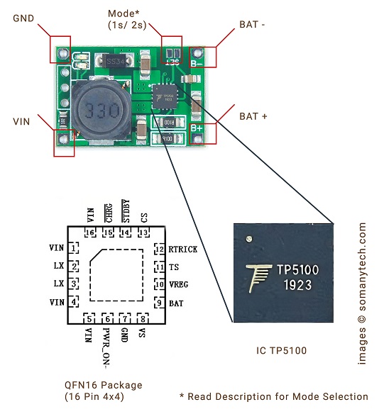
| Pin | Remark |
|---|---|
| 1,4,5,16 - VIN | Input supply voltage |
| 2,3 - LX | Power drain MOS-FET connection |
| 6 - PWR_ON¯ | Enable/Disable IC (Float) |
| 7 - GND | Ground return |
| 8 - VS | Positive feedback for output current detection |
| 9 - BAT+ | Battery positive |
| 10 - VREG | Internal power supply |
| 11 - TS | Temperature sense of battery (refer to datasheet) |
| 12- RTRICK | Trickle pre-charge current set |
| 13 - CS | Chip select input (Float) |
| 14 - STANDBY¯ | Charging indicator |
| 15 - CHRG¯ | Full charge indicator |
Specification:
- Switching frequency 400Khz, usable inductance 22uH/ 33uH and more.
- Size: 25 * 17 * 5mm ultra-small size.
- Input operating voltage: 5-18V DC power supply.
- PWR_ON Power battery for switching control.
- Absolute maximum voltage: 20V
- Operating temperature range: -40 ° to 85 °
- BAT Short-Circuit Duration: Continuous.
- Chip temperature protection, over-current protection, under-voltage protection.
- Battery temperature protection, reverse battery shutdown, short circuit protection.
- Steady pre-charge current programmable to 10% -100% of charging current.
TP5100 Application:
Portable equipment, lithium battery various chargers, Smartphone, Audio Bluetooth players, Industrial commercial power supply maintenance.
TP5100 Module Schematic, Wiring diagram & Connection
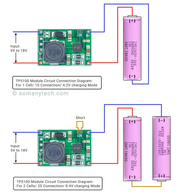
Below is the simple TP5100 Charging module schematic diagram for single cell li-ion and dual cell. The main IC of the module is the TP5100 chip, which is from manufacturer ‘Top Power ASIC’. It has become quite popular for charging 3.7V li ion batteries as it has all the required battery protection feature like over-charge, short circuit, under voltage and over-temperature protection.
For single battery circuit it uses the 4.2V charging voltage by default, but for dual cells in tp5100 charging module needs to connect ‘SET’ on the module board for 8.4V operation.
Click here! for Simple Battery Charger using TP4056
TP5100 Schematic Circuit Diagram
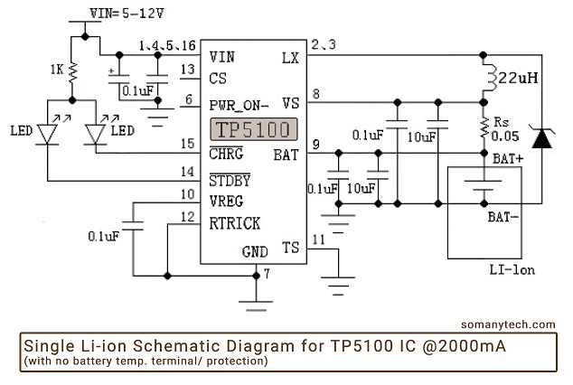
Below is the simple circuit diagram for the Li-ion battery charger schematic according to the datasheet of TP5100 with temperature sense disabled.
The Red LED glows when the battery is charging or module is in standby mode, and the Blue LED glows when the battery is fully charged. These indicators are connected to pin number 14 and pin number 15 respectively.
So here’s the TP5100 1s connection for single 3.7V li-ion battery.
The TP5100 module 2s connection manual for dual 3.7V li-ion batteries in series and 8.4 V is selected with ‘SET’ (short circuit).
Components required:
IC TP5100, 2x LED indicator, 3x Cap= 10.1uF (0.1uF || 10uF), 1x Cap= 0.1uF, Ind=22uH or 33uH, 1x Resistor= 1KΩ, Rs= 0.05Ω (2 x R100 SMD resistor 0.1Ω || 0.1Ω), 3.7V Lithium cells, micro USB/ USB C female connector, customized PCB.
Description:
This circuit can be used only for rechargeable battery charging purposes. Here, Rs is chosen to be 0.05Ω for 2000mA of output current. If we talk about TP 5100, it is a switching dc-dc buck regulator. Thus, in Mode 1 (1S), it is required to supply ~5V, and in Mode 2 (2S), it should be ~12V for intended operations.
Mode 1 (Default): You need to just connect 1 Lithium battery across BAT+, BAT- (GND); that’s all, the module will take care of charging process.
Mode 2 (SET): You need to connect 2 Lithium battery in series across BAT+, BAT- (GND); and Connect CS/ Pin 13 with VREG Pin 10 (for module pin “SET” to be connected) for correct charging process.
The charging current (IBAT) of the li-ion cell can be set manually by choosing the value of Rs. In all the modes during charging, the charging current could be determined as follows. The Rs(Ω) vs Ibat(mA) can be determined using the following table :
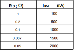
Note: If you have two 18650 lithium batteries, then by connecting them in series (short-circuit “SET” connections), each battery will charge at 1000mA of current. If you connect one Li-ion battery then it will charge it at the rate up to 2000mA, thus it will charge faster compared to TP4056 module to fully charge a battery.
Link to TP5100 Datasheet pdf with pin diagram for detailed analysis. TP5100 Datasheet Download
TP5100 Vs TP4056
There are several Charge Controller ICs available in the market, but here discussed popular ones are TP5100, and TP4056. It will help you choose the right one for your application.
TP5100 is an upgraded version of TP5000 with a maximum charging current of 2A. TP4056 is another charge controller IC with a maximum charging current of 1A.
| IC TP5100 | IC TP4056 | |
|---|---|---|
| Max. charging current | 2000mA | 1000mA |
| Li-ion cell | 1s, 2s (single & dual cells) | 1s (single cell) |
| Operating voltage/ Input | 5V to 18V | 5V to 8V |
| Charge voltage | 4.2V, 8.4V | 4.2V |
| Charging voltage control accuracy | >1% | ~1.5% |
| Initial current | no soft-start | soft-start limits inrush current |
In conclusion, TP5100 is a more advanced and flexible charge controller IC than TP4056. However, if you are looking for a simple and low-cost charge controller IC, TP4056 may be the right choice for you. The TP5100 is a good option for charging dual-cell lithium-ion or lithium-polymer batteries in power efficient applications.
Before choosing a charge controller IC, it is important to consider the requirements of your application, such as the charging current and charging time.
FAQ:
How many batteries can charge in TP5100?
You can charge one, two or more lithium battery cells with TP5100, but note that it has a max 2000mA of charging current. So, when charging multiple cells, you have to connect them in parallel. Also, the charging current will be divided among them, which will make charging slower. It is recommended to utilize two to four cells at a time with this module.
What is the output current of TP5100?
The maximum output current of TP5100 is 2000mA. It can be programmed to provide charging current from 100mA to 2000mA by changing the value of Rs.
What is the use of TP5100 module?
The TP5100 Module is used to charge either single or double 3.7 lithium-ion cell/ battery at 2Amp of current.
What is the input voltage of TP5100?
The input voltage of TP5100 is minimum 5V for single cell and 12- 18V for dual 3.7 lithium-ion cell.


