TC4056 Lithium Ion battery charger- Datasheet & Schematic
The TC4056 is a linear li-ion battery charger IC that is generally used in devices to charge 18650 li-ion cells. This is a charge controller IC which is designed to be used with all 3.7v of lithium ion cells, including Li-Polymer, Li-ion, and LiFePO4 batteries. In this article we will be discussing the circuit diagram of the TC4056 Lithium Ion Battery Charger module, components on the module.
If you are looking for alternatives to TC4056A then, there are several li-ion battery charger ICs such as the TP4056, TP5100, and TP5000. These ICs have similar functions to that of the TC4056A, but they have slightly different specifications, features and application.
Check TP4056 circuit diagram for 18650 battery charging here
The TP4056, TP5100, and TP5000 are alternatives to the TC4056, and they can be used as a substitute charge controller. Before selecting an alternative IC, it is essential to carefully examine the specific requirements of the application.
TC4056 Schematic & Circuit diagram
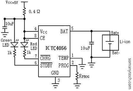
Below is the simple circuit diagram for the 3.7 V battery charger schematic according to the datasheet of TC4056 with temperature sense disabled. The circuit diagram for the TC4056A is simple, consisting of the main IC and a few supporting components such as resistors, capacitors, and LEDs. The schematic includes the input and output connections, as well as the output current control.
In the charging phase, only the Red LED glows, and in the fully charged state, only the Green LED glows. These indicators are connected to pin number 7 and pin number 6 respectively.
So here’s the diagram: How to wire a TC4056?
Components required:
IC TC4056, 2x LED indicator, 2x Cap= 10uF, Rprog= 1.2KΩ, 2x Resistor= 1KΩ, Rs= 0.4Ω, 3.7V Lithium cell, micro usb/ usb c female connector, pcb.

Note:
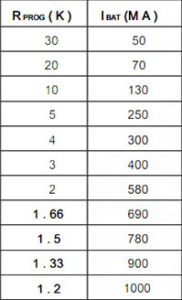
This circuit can be used only for charging purposes. Rprog is chosen to be 1.2KΩ for 1000mA of output current, this can be changed by setting different values of Rprog. If Rprog is chosen to be 2KΩ then battery will be charge at 580mA of output current.
You can manually set the charging current (IBAT) of the lithium ion cell by selecting a value for the Rprog value. In all modes during charging, the voltage on pin 2 can be calculated with respective to charging current as follows:
![]()
The Rprog(KΩ) vs Ibat(mA) can be determined using following table:

The TC4056A and its alternatives ICs have the battery protection features to ensure safe and reliable charging. Like, it has over-voltage protection, which prevents the battery from being charged to a voltage level that is too high. It also has thermal protection, which cuts off the current when the chip gets overheated due to any reason, and also has short-circuit protection.
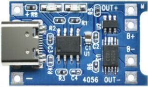
TC4056 Module:

IC TC4056 is also available as a module, which has all the components on board required for functioning. This module makes it easy for DIY projects, as it eliminates the need for manual soldering and component placement. TC4056A modules can be purchased online or through electronic component distributors.
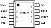
TC4056 Pinout:
The TC4056 has a total of eight pins, all of them are used in the schematics. The pinout of the TC4056A is as follows:

- VCC+: This is the positive input terminal.
- PROG-: This is the terminal for determining the charging current.
- BAT+: This is the positive terminal of the battery being charged.
- CHRG: This is the indicator pin of the battery being charged.
- STDBY: This is the status output pin, which indicates the battery is not connected.
- GND: This is the ground pin.
- TEMP: This is the thermal protection pin, which provides protection against overheating.
- CE: This is the charge enable pin, ie., switch for charging process.
The pinout of the TC4056A and its circuit diagram are also straightforward and well-documented, making it easy to use in a variety of battery charging applications.
Check the datasheet of TC4056 here


