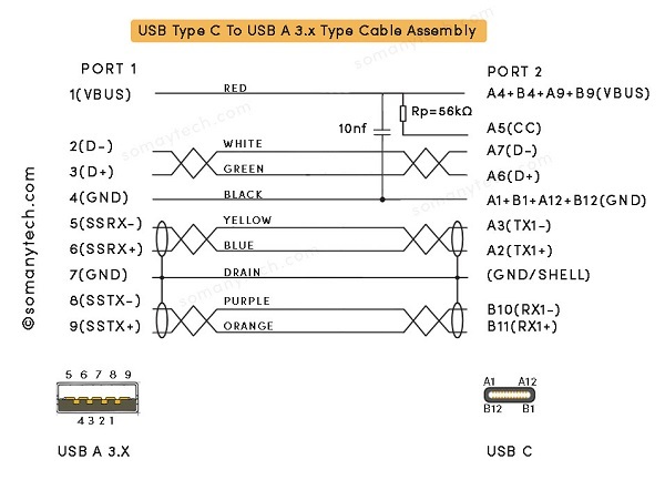
USB C 3.0 Wiring Diagram – Detail Internal Connections
The USB implementer Forum sets the standards for data transfer through various cables and connectors one can use on the end of those cables, that also includes USB communication protocols. This post will take you to the USB C wiring diagram/ USB C 3.0 wiring diagram and related information in detail.
USB 3.1 Gen 1 which is formerly known as USB 3.0, later renamed USB 3.2 Gen 1×1 port.
This means that USB 3.0 is the same as USB 3.1 Gen 1.
Also, USB 3.1 Gen 1 is the same as USB 3.2 Gen 1×1.
This can be concluded that all USB 3.0/ USB 3.1 Gen1/ USB 3.2 Gen 1×1 are having same hardware interface and USB protocol. All new generation USB 3.x are made backward compatible to USB 3.0 and 2.0; USB Type-C to USB-A Male 3.1/ 3.2 Gen2 Adapter charger cable supports data transfer rate upto 10Gbps
USB C wiring diagram to male USB 3.1/ 3.2 type A Gen1/ Gen2:

As you know that USB C 3.x is made to be operated reversibly, also by looking at pin out diagram of USB c male you can see that all the pins termed A could be interchangeably used with that of termed B. check USB Type C 3.0 pinout!!
Also check USB C wires Color Code here!!
The table shows below the connection between pins on both the end of the plugs and their functions with respective symbols:
| Signal Name | Port 1 | Conductor Color | Port 2 | Signal Name |
|---|---|---|---|---|
| VBUS | 1 | RED | A4,B4,A9,B9 | VBUS |
| D- | 2 | WHITE | A7 | Dn1/ D- |
| D+ | 3 | GREEN | A6 | Dp1/ D+ |
| GND_DRAIN | 4 | BLACK | A1,B1,A12,B12 | GND |
| N/A | - | N/A | A5 | CC |
| N/A | - | N/A | B5 | VCON |
| SSRX- | 5 | BLUE | A3 | TX1- |
| SSRX+ | 6 | YELLOW | A2 | TX1+ |
| SSTX- | 8 | PURPLE | B10 | RX1- |
| GND_DRAIN | 7 | - | GND | GND |
| SSTX+ | 9 | ORANGE | B11 | RX1+ |
| SHIELD | SHELL | N/A | SHELL | SHIELD |
- According to the USB standard, VBUS carries a +5v and the default output current of up to 3.0A.
- Pin no.1 from USB type A 3.1 male is connected to the Pin no A4, A9, B4, B9, of USB type C. This pin is named as the (+VDD/ VBUS) through which the power is supplied to the device or any equipment which is also an indicator of handshake signal, that convey the system that “the device is connected”.
- Pin no.4 from (Port1) USB type A 3.1 male is connected to the Pin no A1, A12, B1, B12, of (Port2) USB-C. This pin is the ground return (GND). This is individual black color wire.
- Pin no.3 from USB 3.1 type A male is connected to the Pin no. A6 of port 2.
Pin no.2 from USB type A male is connected to the Pin no. A7 of port 2.Both Pin no. 2/A7 (D-) and pin no. 3/A6 (D+) are used as a differential data pin in each port. Data is sent from and received from these port when used in USB 2.0 mode (in reverse compatibility mode with previous generation USB host) - Pin 7 is connected as a Drain/Shell.
- Pin no. 5 (SSRX-) from port 1 is connected to Pin no. A3 (TX1-) of port 2, Pin no. 5 (SSRX+) from port 1 is connected to Pin no. A3 (TX1+) of port 2.
- SSTX are bidirectional data SuperSpeed Transmitter ends.
- Please note that SSRXp1 can be written as SSRX1+, also SSRXn1 can be written as SSRX1-
- Pin no. 8 (SSRX-) from port 1 is connected to Pin no. B10 (RX1-) of port 2, Pin no. 9 (SSRX+) from port 1 is connected to Pin no. B11 (RX1+) of port 2.
- SSRX are bidirectional data SuperSpeed Transmitter ends.
- Please note that SSTXp1 can be written as SSTX1+, also SSTXn1 can be written as SSTX1-
Also check USB OTG wiring diagram.
USB type C terminologies and parameters for technical/ manufacturing use:
- Pull-up resistor (Rp): The pin A5 /(CC) is connected in series with resistor Rp= 56kΩ with the +5v (VBUS) at USB C plug terminal. The value of Rp determines the current sourcing capability of the Type-C ports for which it is designed.
- SHELL/ SHIELD/ BRAID: For a good quality USB cable, to avoid crosstalk and RF interference from adjacent data lines, it is recommended to have 360-degree conductive shielding with ground shield termination on both ports.
- The main purpose of shielding is to prevent unwanted RF interference and noise signals.
- In common practice, A6 and A7 are un-shielded pair of wires, (B10+B11) and (A2+A3) are shielded pairs of wires respectively, shield is individually grounded at both end, remaining ground connection should be individual black color conductor. Also check different USB mode here


