9v to 5v Converter – 4 Simple circuits for Projects
Before jumping to the 9v to 5v converter circuit using different schematics, lets discuss the topic in short. There are wide range of IC’s and devices that requires 5 V DC supply for their operation. When working with a 9V battery supply, it becomes quite difficult to get a 5V dc power supply for the circuits. Here are the simple circuits that provide +5V from a 9V radio battery. Below are listed all the possible circuits, but their application differs from circuit to circuit.
These circuits are basic voltage regulators, the first one is a simple voltage divider using resistors. All the circuits have different performance. The voltage divider circuit is not recommended for use in the high current application as it has a low output current and lower efficiency.
LM7805 9v to 5v converter:
A 9v to 5v voltage regulator can be implemented with an LM7805 step-down voltage converter. It is used for (10mA to 1 Amp and more) medium to a high current application.
The unique about this circuit is its ability to provide the same output current as applied at the input end.
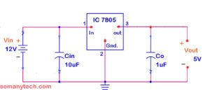
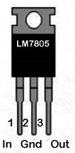
One needs to connect the input capacitor and an output capacitor to the IC 7805 to work as stated according to the datasheet. The heat sink is a must because the voltage drop of 4 volts is to be dissipated as a heat though the Heat-Sink. The absence of heat-sink will destroy the IC and you will be with a damaged IC. The input voltage must be at least 2.5V greater than the rated output voltage.
Components required:
One 9v battery/ 9V adopter power supply, 10uF capacitor, 0.1uF capacitor, IC LM7805, Heat-sink, some wires or connectors, and soldering iron.
Working:
For obtaining a steady and reliable output voltage, the voltage regulators IC’s are used. The integrated circuits that offer linear voltage conversion and regulation are often named as transformer ICs. Here, we have discussed 9v to 5v DC converter using IC 7805. The transformer IC 7805 is part of the LM78xx series of transformer ICs. It is a linear transformer IC. The digits ‘xx‘ represents the value of the output voltage regulated.
The 7805 IC gives 5V DC as the digit ‘xx‘ showing (05). The input voltage can up to 35V, and the output will be constant 5V for any value of the input. Pin 1 is the input supply terminal. Pin 2 is the ground terminal. Pin 3 is the output power supply terminal.
Check this video for reference: (input capacitor is not used, but it is recommended, also values of capacitor may be different as available and depending on the area of application)
Check this simple 12v to 6v converter circuit
LM317 9v to 5v converter:
A 9v to 5v dc converter can also be implemented with an LM317 voltage regulator. It is useful in mid to high current (1 Amp and more) applications.
This circuit also has its ability to provide the same output current as given at the input end.
Generally, LM317 is used as a variable power supply that can provide variable output voltage (1.25V to 37V) depending on adjust the voltage on pin number 1 (Adj.) which is reference voltage taken from a potentiometer. Here it is a voltage divider circuit using which LM317 gives a fixed output voltage of 5V.
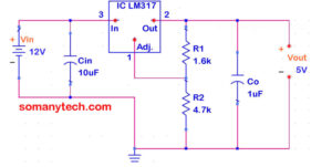
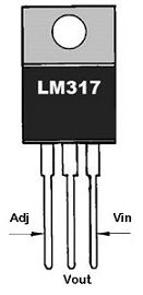
It is suggested to connect input capacitor (also the output capacitor). A heat sink is should be there to dissipate extra potential difference in the form of heat via the Heat-Sink. The presence of heat-sink is a must otherwise it will destroy the IC and IC will exhaust. The input voltage should be at least 1.5V greater than the rated output voltage.
Components required:
One 9v battery/ 9V power supply, a 10k ohm resistor, 2.7K ohm resistor 10uF capacitor, 0.1uF capacitor, IC LM317, a Heat-sink, some wires, and soldering iron.
Check LM317 Resistor Calculator for below formula.
Working:
The LM317 is an adjustable voltage regulator IC competent of supplying more than 1.0 Amp of current with a wide range of o/p voltage from 1.25V to 37V. Its regulation is quite better than fixed voltage-regulator IC like LM7805, LM7806, LM7808, LM7810, etc.

This is the formula for the output voltage of 9v to 5v converter using LM317. It gives approx required output when R1 and R2 are chosen to satisfy the formula. Put any standard value of anyone resistor (above 100 ohms, but a higher value is recommended), also put the value of required output voltage in the above formula and then find the value of another resistor.
9v to 5v converter circuit using a voltage divider:
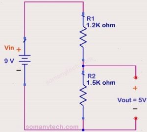
The circuit shown here is the circuit for low current (1-30 mA) applications, suppose we have to take reference voltage for comparison or a very low current drawing circuit of an LED indicator.
You can connect two LEDs in series across the output of R2 resistor if you are using a 9volt battery as an input.
Components required:
One 9v battery, 1.5k resistor, 1.2k resistor, some multi-color connecting wires.
It is a simple voltage divider configuration. You can design the output voltage according to your need by using this formula:

Where, Vo is the o/p voltage taken across resistor R2. Vin is the input voltage. Choose any resistor value, either R1 or R2 (more than 1K Ohm) and calculate the other one. Then pick the nearest standard value of the resistor.
Click here for high speed high current static switch circuit with IRF3205 MOSFET and datasheet.
9v to 5v converter using zener diode:
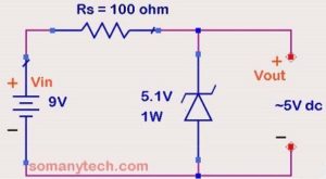
The circuit shown below is for medium current applications, it is useful for (1-100mA) medium current drawing circuit eg. LED indicators, control circuits, transistor switches, LDR circuits.
Use this 9v to 5v converter (step down) circuit with any other circuit in parallel to the output of zener diode (with a 9volt battery as an input). You will get approx. 5V at the output.
Important:
The load must be connected all the time at the output end while testing or while using it in a circuit to prevent a zener diode from being damaged.
Components required:
One 9v battery, 100-ohm resistor (≥22 ohms), 5.1V zener diode (≥1W), some wires or connectors.
Working:
It is the most common circuit of a zener diode in voltage regulator configuration. You make the output voltage work according to you by changing a zener diode ratings and Rs (series resistor).
Design a ‘Vo’ stabilized power supply is to produce from a ‘Vs’ DC power supply source. The maximum power rating PZ of the zener diode is in ‘W’. Using a zener regulator circuit and calculate using the following formulas:
The maximum current flowing through the zener diode.
Id = (Watts / Voltage)
The minimum value of the RS series resistor.
Rs = (Vs – Vz) / Iz
The load current IL if a load resistor of 1kΩ is connected across the zener diode.
IL = VZ / RL
The zener current IZ at full load.
Iz = Is – IL
Where,
IL = current through Load
Is = current through Rs series resistor
Iz = current though zener diode (assume 10- 20mA if not given)
Vo =VR =Vz = zener voltage = output voltage
RL = Load resistor
*Before applying this 9v to 5v converter circuit in projects, verify the output voltages to ensure proper working of the circuits. The current value described in the article is for reference only, as the value of current depends on the load resistor.


