5v to 3.3v Converter Circuit and Module – Detail Schematics
Certain electronic devices, components, IC’s, sensors or microcontrollers designed to work on 3.3V DC supply as a power source.
While working on some projects with standard power supply (say) 5 volts or higher, some modules/ circuits would require lower 3.3Volts. Here, in this post we will be discussing some of the simplest voltage regulator circuits designed using linear regulator IC LM/ AMS1117, LM3940, etc.
These circuits can also be used to step down or reduce 5V/ 9v available supply potential to 3.3v so as to use it with microcontroller, modules or any IC’s.
A 5v to 3.3v converter circuit can be implemented using various ways like using linear voltage regulator, boost converter/ switching converter, resistor/ voltage divider, zener regulator, etc. You could choose the right circuit or module according to the requirements of the applications.
It is always recommended to use reliable linear power converters like ASM-LM1117/ LM3940/ XL6009 etc.
5v to 3.3v converter with LM1117/ ASM1117
LM1117 3.3V is a fixed voltage linear regulator IC that reduces and regulates the higher input voltage to a fixed 3.3V DC. It is suitable for low current application as well as for the current up to 800 mA.
IC AMS1117 comes with several variants, hence pick the proper IC. By using this linear voltage regulator circuit, we can convert 5V to 3.3V without taking up a lot of circuit space.
IC LM1117 3.3 v circuit is implemented as shown in the schematic diagram below:
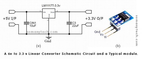
Components required:
- 1X 10uF capacitor
- 1X 22uF capacitor
- IC LM1117T- 3.3v or ASM1117- 3.3V
- Heat-sink, wires, and connectors.
Features:
- This IC has built-in features like current limiting and thermal protection, and thermal shutdown.
- Low dropout voltage regulation with a dropout of 1.2v
- Delivers output current upto 800mA
- Output voltage accuracy within ±1%
- Fewer external components
LM1117 is an IC of LM1117x series; the different ICs in this series are made for different output voltages. A common use for these ICs are in regulated power supply circuits.
Click here to check 9v to 5v converter circuit
ASM1117 is an alternative to LM1117, they could be used as a replacement for each other.
An adjustable version of the LM1117 is also available, this version can be set to output voltages ranging from 1.25 to 13.8 V using only two external resistors. Additionally, it is available in five variations of fixed voltage, 1.8 V, 2.5 V, 3.3 V, and 5 V.
For pin-out diagram of LM1117 3.3 V circuit, the Pin 3 is the input pin, while Pin 1 is the ground pin and Pin 2 is the output pin.
Applications:
AC drive power stage module, Industrial AC/DC applications, Ultrasound scanners, servo drive control modules.
(video for reference only, you can replace capacitor value according to applications and availability)
(Scroll down for more detailed information on this module IC, check the datasheet at the end of the page)
Check simple 5V to 12V converter circuit
LM3940 5v to 3.3v converter circuit:
The LM3940 is a 1 ampere low-dropout regulator designed to provide a 3.3V regulated output from a 5V supply. It is useful for medium current range of up to 1 Ampere.
The LM3940 is ideally suitable for systems where both 5V and 3.3V logics are required. As the LM3940 has a minimum 1.2V dropout, it is able to maintain 3.3V regulated output with input voltage as low as 4.5 V.
Due to its TO-220 package, the LM3940 is capable of delivering 1 A of load current without the need for additional heatsink.
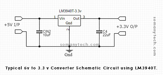
Components required:
- 5V power source
- 10uF capacitor
- 33uF capacitor
- IC LM3904- 3.3 V
Features:
- Wide input range of 4.5V to 5.5V
- Specified 1A output current
- Short circuit protection
- Built-in over-heat protection
Pin 3 is the output pin. Pin 1 is the input pin. Pin 2 is the ground pin. The output voltage at pin no. 3 may vary between 3.20 to 3.40 volts. The typical output will be 3.3 volts when junction temperature Tj=25℃.
For pinout diagram and detail technical information on this IC check datasheet at the end of the page.
Application:
Motherboards of computers/ laptop, logic systems, power supply to IC’s, modules and peripherals.
You might be interested in 3.7v to 5v boost converter circuit
5v to 3.3 v dc dc boost converter using Xl6009:
Using the dc dc boost converter module with IC XL6009, you can achieve 3.3V stable DC voltage output at the input voltage level of 5.0V. It incorporates an N-channel power Mosfet and oscillator, and its current mode architecture provides stable operation across a wide input voltage range.
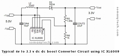
Components required:
Ic XL6009
Inductor L≥33uH
Switching diode (Schottky diode) D1=SS34
2 ✕ Capacitor C≥22uF
R5 = 1.65 kΩ
R6 = 1 kΩ
For required output, this programmable IC needs to be configured by changing the feedback voltage(FB), which is done by changing the value of R5 And R6.
The value of R5 and R6 can be determined using this formula:
Vo=1.25(1+R5/R6)
Where 1.25= Vref (reference voltage of the IC)
Here, we need Vo = 3.3V, then assume the value of either R5 or R6 then find for the other.
E.g. choose R6=1.0kΩ, put the value in the formula, we get R3=1.65kΩ. Hence, the values.
Contains a thermal shutdown feature, preventing the module from overheating in the event of a circuit failure. Operating at a frequency range of 400-480KHz, this boost converter typically delivers an output efficiency of 94%.
Features:
- Wide input voltage ranges from 5V to 32V
- Ripple/ Voltage regulation: ± 0.5%.
- Typical conversion efficiency: ~94%.
- Refer to the datasheet/ module specification for precise technical parameters.
Application:
High efficiency DC to DC voltage conversion, electronic device applications, etc.
5v to 3.3v converter using zener diode:
The circuit shown below zener voltage regulator schematic, it is useful for medium current drawing circuit e.g. LED indicators, transistor switches, Arduino modules etc
Use this 5v to 3.3v zener regulator (DC to DC) circuit to get required 3.3 volts. You will get approx 3.3V at the output.
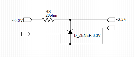
Components required:
20-ohm resistor (≥10 ohms), 3.3V zener diode (5W), some wires or connectors.
Important:
The load must be connected to the output end to prevent zener from getting damaged. A series resistor 20 ohms is a current limiting resistor and when high current is drawn, to avoid damage a 5-watt resistor should be used.
Working:
It is the most common circuit of zener diode in voltage regulator configuration. For detailed calculation and formula, click here > zener regulator part of this post.
5v to 3.3 v resistor circuit as a voltage divider:
Voltage divider circuit 5v to 3.3 v resistor has somewhat limited applications. The schematic shown below is the circuit for low current applications, or to take reference voltage in a comparator circuit or low current drawing circuit of an LED (output current also depends on load resistance).
You can drive a LED in across the o/p of R2 resistor if you are using a 5 volt power supply at the input end.
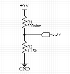
Components required:
590-ohm resistor and 1.15k resistor
It is just a voltage-divider circuit. You can get the output according to your need with this formula:

Whereas, Vo is the o/p voltage. Vin is the input voltage. Choose either R1 or R2 as your resistor value and solve for other. Then select the nearest standard value of the resistor.
Datasheets of Boost converter IC:
Datasheet and pinout diagram of IC LM1117 3.3 v circuit
Datasheet and pinout diagram of IC LM3940 3.3 v circuit
(all the IC’s and datasheet mentioned here are strictly belongs to respective semiconductor company)
Conclusion:
The consolidated effort has been taken to conclude the best possible simplified information on these linear voltage converter/ boost converter ICs, the ultimate aim of this article is to put forward how to use popular predesigned ICs/ modules available in the market.


