Best 3.7v to 5v Boost Converter Circuit & Module
Looking for the 3.7v to 5v boost converter circuit diagram? So here we will be discussing some of them, using high-efficiency DC to DC switching regulator IC. These step-up DC to DC boost converters are usually ready-made modules available on sale online.
There are many to choose from, but this post will take you through the boost converter module designed with the popular switching regulator ICs.
It is suggested to just purchase a DC to DC Step-up module for just a power supply needed in a project around a micro-controller or to drive the peripherals. This is because some modules come with an adjustable output voltage that would come in handy if required in different scenarios. Also, it is designed in a compact space.
If you are someone making a project that is around a buck converter/ power supply circuit, then information on this page would be very useful for you.
Keep reading, as in this post you’ll walk through the introduction and circuitry of DC to DC Boost Converter & Power Modules, also covering the data sheet, pin-out, features, and intended applications.
We’ll get right into it.
So we can implement 3.7v to 5v using : IC MC2108Axx, MT3608, XL6009, and many more. All the ICs are having PWM, switching and voltage regulating capabilities. Boost buck converter can also be called constant current drivers.
3.7V to 5V Boost Converter using IC MC 2108Axx
With the voltage boost converter module with IC series ME2108Axxx, you can achieve 5V stable DC voltage output at a wide range of input voltage levels between 0.9V and 5V. This small circuit boosts the voltage level and provides the amplified, stabilized 5V output. This IC is designed such that it requires minimal external components.
The amount of current required to produce a stable output varies, depending on the input voltage range. For an input of 3v or more, the output of this IC is limited to a maximum of 480mA at 5V. These DC-DC boost converter modules operate at the frequency ~160KHz, the typical output is 85% efficient.
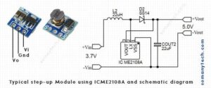
The below image shows a schematic of the simplest 3.7 to 5v boost converter using ME21008A.

Components required:
Inductor L≥22uH
Switching diode (Schottky diode) I=SS14
IC ME2108A series
Capacitor C≥22uF
Features:
- Small in size and lightweight
- Wide input voltage range from 0.9 to 3.7V
- Maximum output current: 480 mA at 5V (at input voltage more than 3.5V)
- The input of 3V gives 5V at ~400 mA.
- Typical conversion efficiency: up to 85%
- Ripple/ Voltage regulation: ± 2.5%
Application:
Battery powered devices/ portable equipment, low current circuits, any module that needs higher voltage from lithium 3.7v volt battery, etc
If you want to use 18650 lithium-ion battery or any 3.7v battery as a 5v battery supply then, check power bank circuit, this might help.
3.7V to 5V DC-DC Step up Converter circuit using IC MT3608
With the voltage boost converter module with IC MT3608, you can achieve 5V stable DC voltage output at a wide range of input voltage above 2.0V. If voltage drops below 1.98V the IC will undergo an ‘under voltage lockout’.
This IC is designed to work with small and lightweight external components so as to be installed in small & compact spaces.
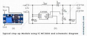
The below image shows a schematic of a 3.7 to 5v boost converter using IC MT3608:

The amount of current required to produce a stable output varies, depending on the input voltage range. For an input of 3.7v or more, the output of this IC’s can deliver a maximum of a 2000mA. (for that, input supply must be capable of delivering higher current). These DC-DC boost converter modules operate at the frequency ≥1.2MHz, the typical output is 93% efficient.
Components required:
Inductor L≥22uH
Switching diode (Schottky diode) I=SS34
IC MT3608 series
2 ✕ Capacitor C≥22uF
R1 = 110kΩ
R2 = 15kΩ
The value of R1 and R2 can be determined using this formula:
Vo=0.6(1+R1/R2)
Where 0.6= Vref (internal reference voltage of the IC)
Here, we need Vo = 5V, then assume the value of either R1 or R2 then find for the other.
E.g. choose R2=15kΩ, put the value in the formula, we get R1=110kΩ. Hence, the values.
Features:
- Thermal overload protection in case of output overload.
- Wide input voltage range from 2.0 to 24V.
- Maximum output current up to 2 Amps at 5V
(for higher η% and optimal performance, input should be voltage more than 3.0V) - Typical switching frequency ~1.2MHz.
- Typical conversion efficiency: up to 93%
Application:
Battery-powered equipment, set-top box, LED bias supply, DSL, Cable Modem and Router, networking cards powered from PCI or PCI express slots.
(Scroll down for more detailed information on this IC module, check the data sheet at the end of the page)
Also check, 3.7v to 12V boost converter schematic
You can also implement 3.7v to 5v using IC LM2596 dc to dc boost converter as this power converter IC is also popularly used everywhere (LM2596 have similar features as that of IC XL6009).
Important note: Mentioned circuit designs are implemented using ADJ versions of voltage converter ICs, keep in this thought that fixed output voltage version of the respective ICs are also available. Make sure to use it accordingly. Check datasheet for part number of fixed version and adj version of all boost converter ICs.
DC-DC Buck Converter circuit using IC XL6009
With the voltage boost converter module/ pwm switching regulator with IC XL6009,
You can achieve 5V stable DC voltage output at a wide range of input voltage levels between 3V and 32V. The XL6009 is designed with an N-channel power Mosfet and oscillator, also its current mode architecture results in stable operation over a wide input and output voltages.
This programmable IC thus needs to be configured by adjusting the feedback voltage, which is fixed by changing the value of R1 And R2. There is a need to use a voltage divider circuit for the required feedback voltage.
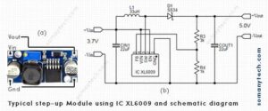
The below image shows a schematic of a 3.7 to 5v boost converter using IC XL6009:

The amount of stable output current required depends on the input voltage and current capacity. The output current of this IC can be tested for different voltages according to the required input voltage. These DC-DC boost converter modules operate at the frequency 400-480KHz, the typical output is 94% efficient.
Components required:
Inductor L≥33uH
Switching diode (Schottky diode) D1=SS34
2 ✕ Capacitor C≥22uF
R3 = 3kΩ
R4 = 1kΩ
The value of R1 and R2 can be determined using this formula:
Vo=1.25(1+R3/R4)
Where, 1.25= Vref (reference voltage of the IC)
Here, we need Vo = 5V, then assume the value of either R3 or R4 then find for the other.
Eg. choose R4=1kΩ, put the value in the formula, we get R3=3kΩ. Hence the values.
Features:
- Compact in size.
- Wide input voltage ranges from 3V to 32V.(optimum operating voltage is 5V – 32V).
- Capable of delivering maximum input current of 4 Amp.
- Typical switching frequency 400KHz.
- Ripple/ Voltage regulation : ± 0.5%.
- Typical conversion efficiency: ~94%.
- Refer to the datasheet/ module specification for more technical parameters.
Application:
High efficiency DC-DC voltage conversion, micro-controller peripheral supply, etc.
Datasheets of Boost converter IC
links
IC ME21008A datasheet
IC MT3608 datasheet
IC XL6009 datasheet
(all the ICs and datasheet mentioned here belongs to respective semiconductor company)
Conclusion:
There are several more ways to execute a 3.7v to 5v boost converter circuit diagram through methods that are not mentioned above. More circuit could be updated in this using different ICs in due time. The consolidated effort has been taken to conclude the best possible simplified information on these modules and IC’s, the ultimate aim of this article is to convey how to use Step-up modules built with popular per-designed ICs available in the market. Use your own consent/ assent/ experience/ observations before reaching a final conclusion.


