Best 3.7v to 12v Boost Converter Circuit & Modules
Looking for the 3.7v to 12v boost converter circuit diagram? In this article, we’ll discuss a few of these, using a high-efficiency DC to DC step-up converter IC. These step-up DC to DC boost converters are generally available as a module on sale online.
There are many to choose from, for this post we will focus on the boost converter module based on the popular DC- DC switching regulator IC.
It is suggested to buy a DC to DC Step-Up module for just a power supply needed in a project around a micro-controller or to power the peripherals. The reason for this is that some modules have adjustable output voltages that could be useful in various situations. Also, it is designed in a compact space.
Keep reading, as in this post you’ll walk through the introduction and circuitry of DC to DC Boost Converter & Modules, also covering the datasheet, pinout, features, and intended applications.
Let’s get started.
So we can implement 3.7v to 12v boost converter circuit using :LM2577, MT3608, XL6009, and so on
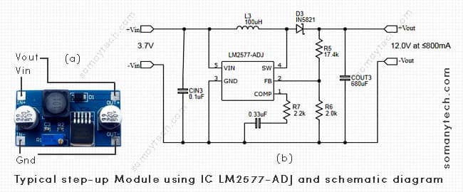
3.7v to 12v Boost Converter circuit using IC LM2577
With the voltage boost converter module using IC Lm2577-ADJ, you can achieve 12V stable DC voltage output at a wide range of input voltage levels as low as 3V and up to 40V. The LM2577 is designed with an 3.0A NPN switch, also combined with a protection circuit consisting of current limiting and thermal limiting.
Consequently, this programmable IC must be configured by adjusting the feedback voltage, which is determined by changing R5 and R6. In order to provide the feedback voltage, a voltage divider circuit is incorporated. These DC-DC boost converter modules operate at the frequency 48-53KHz.

Above 3.7v to 12v boost converter circuit is implemented using variable output IC Lm2577-ADJ.
This can be implemented using a fixed output 12v switching IC Lm2677T-12 which comes under the lm2577 series step-up voltage regulator.
Components required:
IC Lm2577-ADJ
Inductor L3≥100uH
Switching diode (Schottky diode) D3=IN5821
Capacitor: Cout≥680uF, Cin=0.1uF, Comp=0.33uF, R7=2.2kΩ
R6 = 2.0kΩ
R5 = 17.4kΩ
The value of R5 and R6 can be determined using this formula:
Vo=1.23(1+R5/R6)
Where 1.23= Vref (reference voltage of the IC)
Here, we need Vo = 12V, then assume the value of either R5 or R6 then find for the other.
Eg. choose R6=2.0kΩ, put the value in the formula, we get R5=17.4kΩ. Hence, the values.
There could be a difference between ‘Operating Ratings’ and ‘Absolute maximum Ratings’ of the boost up converter. They could also operate at absolute ratings, but it is recommended to run them under maximum operating ratings. And for that you might need to refer to the datasheets.
Check 5v to 12v dc dc boost converter schematic circuit here
Features:
- Requires few external components.
- Soft start function (low initial current to avoid current ripple/ spike, helps reduce high in-rush current during start-up).
- Capable of handling maximum output current up to 3.0 Amp and maximum output voltage of 60V .
- Internal oscillator having 52KHz frequency.
- Conversion efficiency up to 92%, (higher the output voltage higher is the efficiency).
- Refer to the datasheet/ module specification for more technical parameters.
Application:
Simple boost regulator, fly-back and forward regulators, multiple output regulators.
You can also use this circuit as 5v to 12v converter, the reason behind this is that according to the datasheet this IC can convert any voltage above 3v to required voltage.
You can check 3.7v to 5v boost converter circuit here.
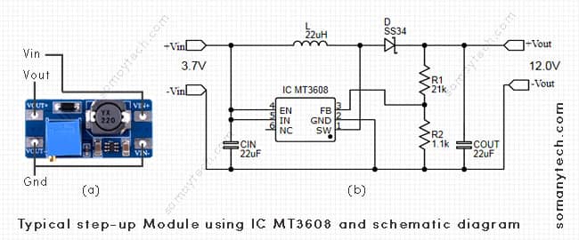
3.7v to 12v Step up Converter using IC MT3608

Components required:
IC MT3608 series
Inductor L≥22uH
Switching diode/ (Schottky diode); D=SS34
2 ✕ Capacitor C≥22uF
R1 = 21kΩ
R2 = 1.1kΩ
The value of R1 and R2 can be determined using this formula:
Vo=0.6(1+R1/R2)
Where 0.6= Vref (internal reference voltage of the IC)
Here, we need Vo = 12V, so let’s take either R1 or R2 as our starting point and find for the other.
Eg. choose R2=1.1kΩ, put the value in the formula, we get R1=21kΩ. Hence, the values.
With the voltage boost converter module with IC MT3608, you can achieve 12V stable DC voltage output at a wide range of input voltage above 2.0V. Under-voltage lockout occurs if the input voltage drops below 1.98V.
This IC is designed to work with small and lightweight external components, serve to be installed in small & compact spaces. Automatically detect light loads, continue to operate without shutting off.
It depends on the input voltage and current, the amount of the maximum stable output current is produced. For an input of 3.7v or more, the output of this IC’s can deliver a maximum of 2.0A. These DC-DC boost converter modules operate at the frequency ≥1.2MHz, the typical output is 93% efficient.
Features:
- Thermal overload protection in case of output overload.
- Input voltage could be between from 2.0 to 24V
- Maximum output current up to 2.0 Amps.
% and at optimal performance) - The typical switching frequency is ~1.2MHz.
- Typical conversion efficiency: up to 93%
Applications:
Battery-powered portable equipment, set-top box, LCD driver supply, Wi-Fi Router.
(Scroll down for more detailed information on this module IC, check the datasheet of IC MT3608 at the end of the page)
Important note: Mentioned circuit designs are implemented using ADJ versions of voltage converter ICs, keep in this thought that fixed output voltage version of the respective ICs are also available. Make sure to use it accordingly. Check datasheet for part number of fixed version and adj version of all boost converter ICs.
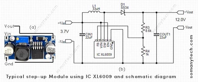
3.7v to 12v DC- DC boost Converter using IC XL6009
Using the voltage boost converter module with IC XL6009, you can achieve 12V stable DC voltage output at a wide range of input voltage levels between 3V and 32V. The XL6009 is designed with an N-channel power MOSFET and oscillator, and its current mode architecture provides stable operation across a wide input as well output voltage range.
This programmable IC thus needs to be configured by changing the feedback voltage, which is done by changing the value of R3 And R4. For obtaining the required feedback voltage, a voltage divider circuit is used.

Components required:
Inductor L≥33uH
Switching diode (Schottky diode) D1=SS34
2 ✕ Capacitor C≥22uF
R3 = 8.6kΩ
R4 = 1kΩ
The value of R3 and R4 can be determined using this formula:
Vo=1.25(1+R3/R4)
Where 1.25= Vref (reference voltage of the IC XL6009)
Here, we need Vo = 12V, then assume the value of either R3 or R4 then find for the other.
Eg. choose R4=1.0kΩ, put the value in the formula, we get R3=8.6kΩ. Hence, the values.
Equipped with thermal shut function, to prevent overheating of the module in case of circuit fault. The output current of this IC can be tested for different voltages according to the given input voltage before application. Typical output efficiency of this DC-DC boost converter is 94% while operating at the frequency range of 400-480KHz.
Features:
- Wide input voltage ranges from 3V to 32V.(optimum operating voltage is 5V – 32V).
- It is able to deliver a maximum output current of 4.0 Amp.
- Typical switching frequency 400KHz.
- Ripple/ Voltage regulation: ± 0.5%.
- Typical conversion efficiency: ~94%.
- Refer to the data sheet/ module specification for precise technical parameters.
Applications:
High efficiency DC-DC voltage conversion, portable electronic equipment applications, etc.
Data-sheets of Boost converter IC
Datasheet of IC LM2577
(all the IC’s and data sheet mentioned here belongs to respective semiconductor company)
The consolidated effort has been taken to conclude the best possible simplified information on these modules and ICs, the ultimate aim of this article is to convey how to use DC- DC Step Up converter modules built with popular pre-designed ICs available in the market. Use your own experience/ observations before reaching a final conclusion.


