Simple 18650 battery charger circuit- Charge controller with Auto cut-off
An 18650 battery charger circuit is specifically used to safely charge 3.7 volt lithium ion batteries. 18650 batteries are lithium-ion cells that are commonly used in several electronic devices such as laptops, bluetooth speakers, portable consumer electronics and power banks. They are called 18650 batteries because they are cylindrical, 18mm in diameter and 65mm in length.
In this piece, we will discuss common 18650 battery charger circuits and popular charge controller modules. Also, it will be helpful for DIY lithium battery charger circuits.
There are different ways to design an 18650 battery charger circuit, all of them have common basic building blocks. This circuit consists of a charging controller, a power supply, and a charging port:
The main block from above is the charge controller. The charging controller regulates the charging process to ensure that the battery is charged safely and efficiently. The charge controller sets and monitors the battery’s voltage and charge current to determine according to specific needs of a particular lithium battery. It also prevents the battery from being overcharged and deep discharge. This helps increase the life of a lithium battery and thus the device.
The power supply could be any AC adapter, a USB port, or a solar panel. The power supply provides stable DC voltage that directly can’t be used to charge li-ion batteries, thus a charge controller is used. The charging port is usually a female DC jack or a micro USB port. The charging port is an input to the charging controller, which monitors the battery and controls the charging process.
also check –> 5 ways to charge 18650 battery
18650 battery charger circuit using TP4056 charge controller IC:
The TP4056 is a popular and most widely used battery charging controller IC. It is a simple and cost-effective IC that is designed for low-power portable electronic devices such as power banks. One of the main advantages of the TP4056 IC is its low cost and simplicity. It has a simple circuit and does not require any additional components to function. It is also widely available and can be easily purchased from online retailers or electronics suppliers.
The TP4056 IC has a built-in charge controller and voltage regulator that is capable of charging lithium-ion or lithium-polymer batteries. It supports USB and AC/DC power sources, and has several safety features to protect the battery and the charger from being damaged.
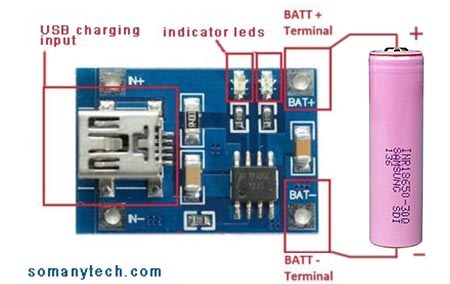
You could implement an 18650 battery charger circuit using TP4056 in two ways, one directly with the TP4056 module available in the market and other with the TP4056 charger IC. Both are discussed and explained in detail below:
Check best simple power bank circuit here
Tp4056 circuit diagram
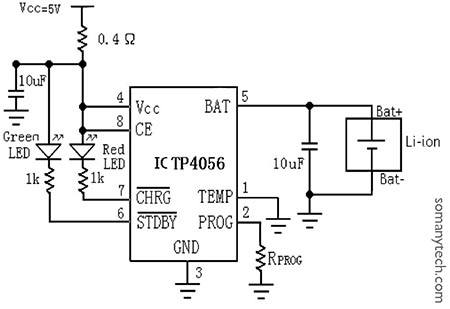
Below is the simple circuit diagram for the 18650 battery charger schematic according to the datasheet of Tp4056 with temperature sense disabled.
Only Red LED glows when the battery is charging and only Green LED glows when the battery is fully charged. These indicators are connected to pin number 7 and pin number 6 respectively.
So here’s the diagram: How to wire a TP4056?
Components required:
IC TP4056, 2x LED indicator, 2x Cap= 10uF, Rprog= 1.2KΩ, 2x Resistor= 1KΩ, Rs= 0.4Ω, 3.7V Lithium cell, micro USB/ USB c female connector, pcb.

Note:
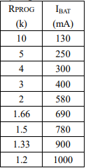
This circuit can be used only for charging purposes. Rprog is chosen to be 1.2KΩ for 1000mA of output current, this can be changed by setting different values of Rprog. If you have two 18650 lithium batteries, then by connecting them in parallel, each battery will charge at 500mA of current. If you connect three then it will charge them at 1000/3 mA each, thus it will take longer to fully charge each battery. To charge 18650 battery with 2000mA current you need to use module with IC TP5100 check here TP5100 circuit and datasheet.
The charging current (IBAT) of the li ion cell can be set manually by choosing the value of Rprog. In all modes during charging, the voltage on pin 2 can be used to measure the charge current as follows:
![]()
The Rprog(KΩ) vs Ibat(mA) can be determined using following table :

Tp4056 module: 18650 Li-ion 3.7 v battery charger circuit

For more technical information, here is the TP4056 datasheet at the end of page or Datasheet of TP4056
Overall, the TP4056 is a good option for charging single-cell lithium-ion or lithium-polymer batteries in low-power applications. It is simple, cost-effective, and widely available, which makes it a popular choice among designers and manufacturers.
FAQ:
How many batteries can charge in TP4056?
You can charge one or more lithium battery cells with TP4056, but note that it has max 1000mA of charging current. So, when charging multiple cells you have to connect them in parallel. Also the charging current will be divided among them, which will make charging slower. It is recommended to charge one or two cells at a time with TP4056 module.
What is the maximum output current of TP4056?
The maximum output current of TP4056 is 1000mA. It can be programmed to provide charging current from 130mA to 1000mA by changing the value of Rprog.


