12v to 9v Converter – Best 5 circuits
If are you looking for a way to power your 9V projects using a 12V power source or a 12v battery then, below is a schematics of the simple 12V to 9V converter circuits. With the right components and some basic knowledge of electronics, you can build your own converter that will step down the voltage from 12V to 9V. These converter circuits designed to use with any micro-controller, modules or any IC’s. Here we mainly use reliable linear power converters like LM7809 and LM317.
In this article, we will provide you an overview of the basic functioning of voltage conversion and guide you through the steps of building a simple 12V to 9V converter circuit.
12v to 9v converter with LM7809:
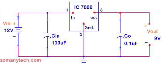
Note that, you have to use the input capacitor ‘Cin’ and an output capacitor ‘Co’ to the IC 7809. The heat sink is necessary because the voltage-drop of 3 volts is to be dissipated as heat. There is a possibility of IC being destroyed if the heat-sink is not connected. The input-output voltage difference here is 3volts which is more than the recommended value of 2.5Volts.
Components required:
A 12v battery/ 12V adopter supply, 100uF capacitor, 0.1uF capacitor, IC LM7809, a Heat-sink, wires, and connectors.
Working:
The IC has a lot of built-in features like thermal shutdown, short circuit protection, and safe operating area protection. LM7809 is an IC of LM78xx series all the ICs in this series are made for different fixed output voltages. These types of ICs are commonly used in regulated power supply circuits.
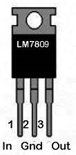
LM7809 a linear transformer IC. The digits ‘xx‘ represents the value of the o/p regulated volts. The 7809 IC gives 9V DC as the digit ‘xx‘ in last represents (09). Pin 1 is the input pin. Pin 2 is the ground pin. Pin 3 is the output pin.
LM317 12v to 9v converter:
A 12v to 9v dc converter can also be made with a versatile IC LM317 linear voltage regulator. It is useful for medium to high current circuits (1 Ampere to 1.5 ampere+) with the proper heat-sink.
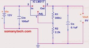
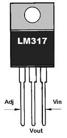
Generally, LM317 is found at variable power supply circuits that give regulated voltage (1.25V to 37V) on changing the voltage on pin no.1. Here, the voltage divider circuit is used with LM317 gives a fixed o/p of 9v.
Important:
It is insisted to add an input capacitor Cin (also the o/p capacitor Co). A heat-sink is a must to cool down the IC from the heat generated inside the IC. The i/p voltage must be at least 1.5V greater than the rated output voltage for this IC to be operated as described.
Components required:
A 12v battery/ 12V power source, a 2.2k ohm resistor, 300-ohm resistor 100uF capacitor, 0.1uF capacitor, IC LM317, a Heat-sink.
Working:
The LM317 is an adjustable voltage regulator IC competent of supplying more than …
(for more detail on LM317 regulator and its working go to this link)
12v to 9v converter using resistors as a voltage divider:
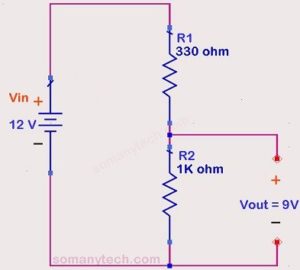
The schematic below shown below is the circuit for low current (~20 mA) applications, or to take reference voltage in comparator circuit or low current drawing circuit of an LED. You can drive three LEDs in series across the o/p of R2 resistor if you are using a 12volt battery in the input end.
This type of circuit is not efficient circuits, thus not recommended for use in project circuits.
Components required:
One 12v battery, 300-ohm resistor, 1k resistor, some wires. It is just a voltage-divider circuit. You can obtain the output according to your need with this formula:

Where, Vo is the o/p voltage. Vin is the source voltage. Pick any resistor value either R1 or R2 (also depends on load impedance) and solve for other. Then choose the nearest std. value of the resistor.
12v to 9v converter using zener diode:
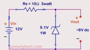
The circuit shown below zener voltage regulator schematic, it is useful for (1-900mA) medium current drawing circuit eg. LED indicators, transistor switches, Arduino, etc
Use this 12v to 9v converter (DC to DC) circuit with any other circuit across the 9.1v zener diode. You will get about 9.1V at the output.
Important:
The load must be connected to the output end to prevent zener from getting damaged.
Series resistor 10 ohm is a current limiting resistor and when high current is drawn it has to pass that current through it, thus 5-watt resistor is necessary.
Components required:
A 12v battery, 10-ohm resistor (≥10 ohms), 9.1V zener diode (5W), some wires or connectors.
Working:
It is the most common circuit of zener diode in voltage regulator configuration. Design 9volt zener voltage regulator from a 12volt power supply source. The maximum power rating …
For detail calculation and formulae search for 9v to 5v converter article on this website.
Simple 12 Volt to 9 Volt DC-DC Converter using transistor:
These types of schematics are outdated but still found in several peripherals. This is the transistor- zener voltage regulator in EC mode:
coming soon…


