What is Insertion loss? What is Return loss?
Insertion loss and return loss are widely used terms in the field of microwave technologies. Insertion loss and return loss plays an important role in designing and development of high-frequency devices such as filters, power dividers, amplifier, etc.
These are quite similar concepts, it is an advanced form of the basic electronics we have learned in network theorems.

What is an insertion loss?
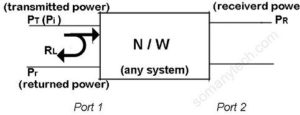
- Technically, when some system or circuit is inserted between a source and a load, some of the signal power from the source is dissipated through the circuit components due to their resistive nature that results in losses.Therefore, not all the transmitted signal power is transferred to the load when the load is connected to the source. The losses thus occurred is called Insertion Loss.
- It is a very important factor while designing and implementing microwave circuits. It is generally expressed in (dB) decibels.
If the power transmitted to the load is PT and the incident power received by the load is PR, then the insertion loss is given by:

What is a return loss?
- Practical circuit realization always suffers a certain level of mismatch between the impedance of the signal source and a load of a system (this load can be a transmission, line antenna, system filters or any device system).Some fraction of signal power inserted is reflected back due to mismatch between two systems, this fraction of power loss is called return loss.
Less power reflection is desirable thus high return loss (RL) is considered good according to the formula:

where RL is the return-loss in dB, Pi is the incident power to the system and Pr is the reflected power from the system.
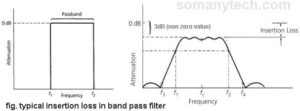
Figure showing insertion loss offered by a bandpass filter, the required signal at another end will have some power loss:

What causes insertion loss?
Insertion loss causes due to two factors namely ohmic loss, dielectric leakage and the return loss is caused due to mismatched systems.
- The first-factor ohmic loss is an unavoidable loss as it is a property of conductor used for connecting the components and the resistor used. Thus, to reduce ohmic losses the components are placed very closely integrated into a small confined area. VLSI and ULSI technology are used for making an integrated circuit that offers high efficiencies.
- In the case of a capacitor, there is some leakage current through it can be reduced but cannot be omitted ideally. This is because of the dielectric in it, thus resulting in power loss.
Miss-matched in the system results in insertion loss and return loss. Ideally reflected power must be equal to zero but, in a practical sense, it has some value that can be up to 10 dB or more even after minimizing these losses.
- As the frequency increases insertion loss and return loss are more relevant in the systems due to the characteristics of microwave frequencies. The voltage standing wave ratio (VSWR) and reflection coefficient (Γ) are an important factor involved in return loss.
- Its basic version we have already learned in the Network theorems. The Maximum Power Transfer Theorem is significantly applicable in microwave frequencies, as the signal power one of the most considered and important factors in RF circuits while designing and implementing filters, amplifiers & power dividers.
- The MPT states that the maximum power is transferred from one circuit to another circuit (or one system to another system) when the impedance of the source is equal to the impedance of the Load.
For maximum power transfer, Xs = Xl
This can be seen as,
When the source impedance is matched with load impedance then ideally return loss must be equal to zero. But practically, it has some value that can be up to 10 dB or more even if the system is matched.
Importance:
- Suppose that you have to transmit a signal through an RF remote control device operating on a small battery. The battery capacity of the remote control is generally very less as remote control must be portable and lite in weight, also long operating hours are expected.
- We need to increase the efficiency of the transmitter used in remote control ultimately do we need to reduce the return loss and insertion loss in the system used in the circuit.Also, the power generated by the transmitter must be efficiently transmitted by the antenna and therefore requires proper impedance matching of output ports of source and the antenna.
It has its applications in the RF sector like Radars and satellite phones.
Relation with the scattering parameter:
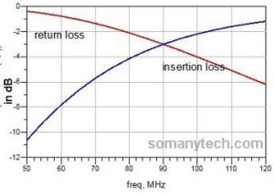
Below image showing insertion loss and return loss for a 90MHz highpass filter matched at 50 Ohms.:

Insertion loss and return loss are linked with the scattering perimeter when the source and the load of the system is matched to the same reference impedance (say 50 Ohms).
S parameters are is the modern way of analyzing two-port networks. It is very helpful in in in optimizing the circuit to its best. It is capable of determining even smaller return loss and insertion loss in the form of s-parameters namely S11, S22, S12, S21:
S12 = transmission coefficient (power gain in dB of the system in a forward direction)
S21 = transmission coefficient (power gain in dB of the system in reverse direction)
S11 = reflection coefficient (related to return loss in dB at port 1)
S22 = reflection coefficient (related to return loss in dB at port 2)
For perfectly matched and ideal n/w:
→ S11 = S22 = 0
-→ S12 = minimum
–→ S21 = depends on the nature of the circuit (≥0)


