Voltage Divider Rule- Formula detail Explanation
Voltage divider rule is one of the most common concept in electronic circuit design. So today we will be discussing in detail the voltage divider formula from where it comes from where the formula is derived along with some practical example. Also mentioned how to design voltage divider circuit for the required output.
While going though electronics basics we face a lots of difficulties learning the formulas, the rules and steps to implement them. But, below topics covered the easy method to learn formulae along with the tricks to remember it.
What is voltage divider rule?
Voltage divider rule is also called as potential divider rule or potential division rule or voltage division rule.
In short, it is assigned as VDR.
Voltage divider rules give the insight of the schematic circuit diagram and applicable formula and its derivation to help with different voltage requirement in the circuit designing.
Voltage divider definition :
> It is defined as the circuit which is used to reduce the large value of the voltage to the smaller value.
> Voltage divider circuit gives the required output voltage as a fraction of input voltage which can be manipulated using formula.
> A voltage divider circuit is a circuit that divides the single voltage value to the multiple output values.
The Voltage Divider is Passive in nature (as it has no active elements) and behavior is Linear (as output is linearly proportional to input)
Voltage divider schematics circuit:
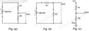
Fig(a), Fig(b) & Fig(c) are voltage divider circuit diagrams.
The image showing three circuits below, they might appear different but fundamentally the same. They are only one circuit with different arrangements and source symbol. Simplifying them you will end up concluding that they are same in electrical rules.

Analysis and Voltage Divider Rule formula:
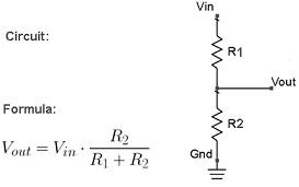
Figure showing a Basic diagram of voltage divider circuit which has two resistors. This is the basic circuit diagram that shows the VDR and its formula. This is very basic circuit and the formula is used for the calculating the output voltage allover while analyzing the circuits.

There voltage divider rule fits in the same concept as Voltage Drop Across Resistor check here!
Voltage divider rule proof and derivation:
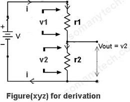
Here, voltage supply is V is connected in series with resistor r1 and r2.

And current ‘i’ is flowing though them causing a voltage drop of v1 across r1 and voltage drop of v2 across r2.
As this is a closed-loop, the current flowing though it will be the same.
For deriving output voltage formulae we need to apply Ohms law across each resistor and the putting the values in equation obtained by KCL (Kirchhoff’s Current Law) as shown below step by step:
According to Ohm’s law we get,
v1 = i☓r1 ———-(I)
v2 = i☓r2 ———–(II)
Applying KVL in the above circuit
V – v1 – v2 =0
ie, V = v1 + v2
By putting the value of v1 & v2 in above equation,
we get,
V = i☓r1 + i☓r2
∴ V= i☓( r1 + r2)
Hence,
i =V / (r1+ r2)
Substituting the value of “i” in (I) and (II)
we get,
v1 = r1☓(V / (r1+ r2))
v2 = r2☓(V / (r1+ r2))
(by adjusting the variables)
Also,
v1 = V☓(r1 / (r1+ r2))
v2 = V☓(r2 / (r1+ r2)) →(note: v2 = Vout) →(III)
(by adjusting the variables for the conditions where we need to find the values of resistors)
Again,
r1 = (v1☓(r1+ r2)) / V
r2 = (v2☓(r1+ r2)) / V
[note: the above formula is very important and has its applications in designing voltage divider circuit]
To be Concluded :
- From equation →(III) we can say that the output voltage is equal to a voltage drop across output resistor (the resistor across which we are taking output)
(check the circuit with 3 resistor in series you will get the point) - The values of the resistor at denominator is nothing but the equivalent resistor of r1 and r2, it can be r1+r2+r3+…+rn, where n number of resistors.
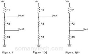
Figure showing voltage divider with 3 resister and its equivalents:

In this circuit (as per the above conclusion from derivations):
→As in Fig. 1 Vout1 is the voltage across resistor R2 and R3
∴equivalent series resistanceR2 and R3 are taken.

→In the Fig. 1, Vout2 is the voltage across resistor R3 only.
Therefore, the equivalent series resistance R3 is taken.

For Fig. 1(a)

For Fig. 1(b)

The practical example of voltage divider circuit (VDR):
Q. Design a voltage divider to give the output voltage of 1.5 volts for designing an amplifier biasing. The given source voltage is 5V.
Ans.
Given→Vo= 1.5V & Vin= 5V
from eq→(III) or simplified formula(look for 1st image of the post)
we have, Vo= Vin.(R2/(R1+R2))
Assuming, R1= 1KΩ
and putting all the values in the formula,
1.5= 5.(R2/(1K+R2))
We get, R2= 0.428KΩ
Q. Design a voltage divider to give the different output voltage of 3 volt and 6 volts for the comparator, given that the input voltage source is having a potential difference of 9 volts.
Ans.
As equal resistor in series offers Equal voltage drop across each resistor.
∴ according to the question,
Vin= 9 Volts, Vout1= 6Volts and Vout2= 3Volts
From this, we can conclude that the smallest output is 3volts and another required output voltage is 6 volts.
Then, we can use three resistor of same values.(say 1kΩ)
∴ R1= R2= R3 = 1kΩ design is completed.
Q. Design a voltage divider to give the output voltage equal to half of the input. The given source voltage is 12V.
Ans.
Given→Vo= 1/2Vin & Vin= 12V
using the simplified formula:
we have, Vo= Vin.(R2/(R1+R2))
Assuming, R1= 10KΩ
put all the values in the formula ∴ 6= 12.(R2/(10K+R2))
We get, R2= 10KΩ
Now design the circuit with these components!!
Q. Can we apply voltage divider rule in parallel circuits?
Ans.
No you cannot apply voltage divider rule in a parallel circuit as it is only applicable to resistors in series. Only the reason that VDR is the modification of Ohm’s law.
Q. Do voltage divider rule only applicable to resistors?
Ans.
No, It can be applied to any passive element like capacitor and inductor. The only thing you have to assume is their impedance (Z).
Instead of the resistor in voltage divider rule, you need to use impedance along with the modified formula of impedance equations.
Zr for a resistor, Zc for a capacitor, Zl for an inductor.
Application of voltage divider rule and circuit :
1) It is used as a biasing circuit in the BJT amplifier.
2) Feedback Circuit in operational amplifier uses the voltage divider rule for driving the input and control the voltage gain.
3) It is the important circuit in comparator that is used for comparing different voltages whether the particular voltage is greater or smaller than the reference voltage.
4) The Logic Level Shifting use the voltage divider formula.
Something important to note:
- When the resistor R1 and R2 are the same, means, it is of the same value then the output voltage is exactly the half (50%) of the original input.
- Also, this circuit implies that it is useful where we don’t have a lower voltage source.
- It can be used as a substitute for the transformer ( only and only if the load is having large resistive impedance, we must use high wattage resistors say 3W/5W, it is very less practically used as it possesses the risk of electric shock)
- You noticed electrical line tester (live wire tester), it is nothing but voltage divider with resistor R1 and resistor R2 which is replaced with a high impedance low current consuming indicator light.


