What is Band Pass Filter – how to design it?
What is a Band pass filter?
Band pass filter circuit is an electronic circuit that is used to pass the frequencies in a particular frequency range so that only a certain frequency is obtained for further processing in the application circuit.”
Alternatively, it can be said that “Band pass filter attenuates all the signal outside the particular frequency range allowing only certain signals to receive.”

The frequency which is allowed, that range of that acceptable frequency is known as pass band. The difference of higher allowed frequency to the lower allowed frequency is called bandwidth of the filter.
This circuit is useful for removing unwanted noise signals by blocking them. The Band pass filter has a lot of applications ranging from audio circuits to the radio frequencies circuits.
Generally, RF bandpass filters are used in transmitters and receivers so that we transmit the data signals to the required destination without interfering with other signals. Because interfering with another signal may cause confusion and cross-talks among the transmitter and receiver.
Importance:
- Filtering is one of the most used methods to get rid of noise in the circuit besides the modulation technique and different other methods.
- These circuits are the weapon for electronic circuit designer who uses this to deal with noise in the circuits special RF receivers in communication devices.
- You can find the simple use of this type of filter in the audio amplifier for driving loudspeakers.
- There you can control the tone of the output music/sound, controlling tone is nothing but the controlling of a pass frequency to the output loudspeaker.
Later on, we will discuss in brief the area of application of the Band pass filter below in the application section
Working of Band Pass Filter :
We have already discussed the working of a low pass filter. The similar is the working of a band-pass filter except for a few extra circuits.
It is the combination of a low pass filter and high pass filter so the formula for cutoff frequency we already discussed {here}
The basic idea of implementing bandpass filter is as shown in the figure:
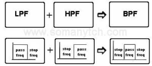
- The ideal bandpass filter and the practical bandpass filter frequency response is as shown in figure. As you see that the Band pass filter has the infinite attenuation for the blocked frequencies and zero attenuation for passband frequencies.
- But in practical this is not possible, the practical bandpass filter offers of zero to one dB attenuation for passive filters which also depends on the type of filter, whether it is RC filter or LC filter? and /or it is passive filter or active filter, which we will discuss below.
Types of Band Pass filter:
Ultrabasic classification is Analog filter and Digital filter. We are discussing here is analog(check below at last for digital filter). Also, basic types of filters are active filters and passive filters.
Active filters are those which require some sort of external power supply(and active components like transistors) to give the required outcome.
On the contrary,
Passive filter does not require any type of active components to do its work and thus preferable in Low-cost circuits.
Now the real bandpass filter is classified into two types based on its bandwidth as follows:
1) Wideband filter.
2) Narrow-band filter /tuned filter.
WideBand pass filter BPF :
The wide-band filter is implemented using One circuit of low pass filter and high pass filter.
- The low pass filter blocks the lower frequencies which are not required and passes all the other frequencies, at the same time the high pass filter blocks the higher frequency than required and passes the frequencies lower than that. Take a look at the following diagram to understand it in a better way.
(BPF using resistor and capacitor,)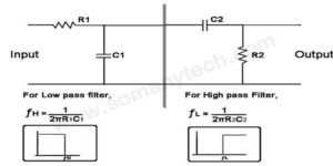
- The wide band filter has quite a lower Q factor. The BPF can be implemented using RC or LC, ie. using a resistor-capacitor for inductor-capacitor.
- The best is to use the Inductor capacitor filter as it has a low power loss. We have discussed the RC filter in low pass filter so we will discuss the LC here in the example below.
Narrow band filter:
- It is also called a tuned filter. As its name suggests that it will pass only a narrow range of frequency through it. The construction of a narrow band filter is quite different.
- The resonance circuit is used to implement a narrow band filter. This is the most favorite filter in all classes of the filter this is because it uses only two components the one is inductor and another is a capacitor in a very simple configuration as shown in the figure. This configuration is called a tank circuit.
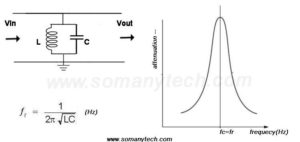
- In this circuit the inductor and capacitor value is chosen such a way that it resonates at a particular frequency, rather say the transfer of charges (current/ energy) from the inductor to capacitor and capacitor to inductor depending on their capacities to hold charges. (This is practically used in various application but lesser taught in the curriculum)
Important definitions:
1) SNR: Signal to noise ratio, it is very important down while designing filters and RF circuits especially transmitters and receivers, also equally important in audio circuits. SNR is the ratio of signal power to noise power.
- Further for ease, the factor used to determine the quality of signal received at the application end is signal to noise ratio.
- The power of the signal must be greater then that of the noise, real noise is the frequencies of unrequired signals which may be natural or artificial for propose full or unintentional.
- Generally, the value of 20 dB for higher than that is considered a good network signal. Similarly, 3dB is a minimum acceptable Value below that value it is very difficult Orra impossible to detect the required signal with accuracy.
2) Q factor: It is lease also called a damping factor it is a dimension list that gives information about the bandwidth with respect to its central frequency. It is used in the circuit having LC in parallel( tank circuit).
Band pass filter example (practical):
Design a bandpass filter having frequency range 80Mhz to 120Mhz?
Given- fc1 and fc2 (where, fc1 =fl =lower cutoff frequency & fc2 = fh = higher cutoff frequency)
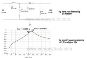
The above circuit is designed using the inductor and capacitor as we have already discussed the upper hand of the LC filter over the RC filter, so we will design the bandpass filter using the inductor.

step1: for LPF
L2 = 10 nH (assumed) & C2 = 0.395 nF (using formula).
step2: for HPf
L1 = 10 nF & C1 = 0.395 nF
(for both LPF and HPF the values came out to be same because for LC filters formula for finding L&C is same only the position of inductor and capacitor interchanges “look fig.”)
Design a narrow bandpass filter having Centre frequency Fc=100Mhz?
Use narrow band pass filter circuit,
Fc=1/2π.sqrt(LC)
Here, the only frequency value is given then how can we calculate the value of L & C ?
-You have to assume the value of any one component either it is an inductor ‘L’ or a capacitor ‘C’.
-Let’s assume, C=1.58 nF (assume the standard value which is available to you)
-then using formula, find L, it came out to be 1.56 nH.
Hence, the circuit is completed. (see image for schematic)
4th order bandpass filter and 5th order Bandpass filter:
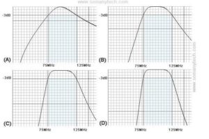
The effect of the orders of filters on the response is displayed in the image below. Just observe the attenuation of the pass frequency and stop frequencies.
- The attenuation roll-off of each is different in different orders of filters.
- The picture is showing 1st order bandpass filter, 2nd order bandpass filter, 4th order bandpass filter, 5th order bandpass filter.
- 1st order filter has -20dB/decade gain roll-off than that of -40dB/ decade for 2nd order filter and so on.
- The order of the filter is achieved by cascading the number of stages of the same filter and sometimes using modern topologies.
Application of Band Pass Filter:
1) Radio transmitter and receiver widely use BPF.
2) Optimization of signal to noise ratio so as to reduce the probability of error in the receiver.
3) In almost every Audio Tone control circuit to increase or decrease the tone in the music.
4) It is an important circuit in demodulators in the receiver circuit.
5) Band selection in FM radio receivers, also in mobile communication systems.
6) In pre-emphasis and de-emphasis circuits to increase S/N.
7) In RADAR to transmit signals in a different spectrum.


