What is High Pass Filter? Its response curve, types, design
Unlike other filters, a high pass filter has its unique importance. The basic mode of communication is voice calling. Of all forms of communication, voice calling is still the most preferred form of communication.
Also, it has challenges while communicating a long distance over the telephone, the only information/data required is voice signal and therefore, it is necessary to maintain the quality of transmitted and received voice signal.
However, a lot of noise interference of low frequency is added to the communication channel. To avoid this highpass filter is used (HPF because the human voice is having a higher frequency than that Of noise).
What is the high pass filter?
A high pass filter is a circuit that allows the higher frequency above cutoff frequency and attenuates all the frequency below the cutoff frequency (ƒc).
As we have already studied low pass filter which blocks low frequency passing through it and only allows higher frequencies to the output, but on the other hand, high pass filter is opposite to that of low pass filter.
 The high pass filter circuit is essential in the day-to-day application in the field of audio applications such as voice recording voice filtering music tone control and so on.
It is widely used for eliminating ‘hiss’ noise, and noise of wind while recording through the microphone in an open environment. We have discussed this in the application section below in detail.
Ideal Vs Practical High Pass Filter

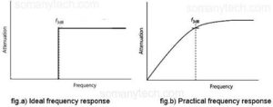
The figure is showing the frequency versus attenuation response curve of the high pass filter. Ideal having very flat response i.e., infinite loss/ attenuation at stop-band and Zero attenuation at passband frequency, but practically due to ohmic losses and lossy components, practical HPF has finite attenuation at stopband and few dB of loss at passband.
The frequency response of High Pass filter:

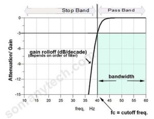
A) -3d dB cutoff frequency is nothing but half of the power at output than at input.
Alternatively, (1/√2=) 70.7{42041a7992ac3be9e9e29c856254fb498d8c7935d7cf8512da6802e8688e734a} of Vin
B) If you have values given in voltage, can be to convert them in dB using this formula:
dB = -20log (Vout/Vin)
Types of high pass filter:
This filter is classified on the basis of the component used to implement the circuit as LC or RC.
A) HPF using R & C:
There are two schematics generally used in the filter. The filter that uses a resistor in the circuit is used in combination with an external power supply called active filter, otherwise passive filter.
The Other method is to design filter using RC and then amplify the signal, that filter without any external power source is called a passive filter.
The figure showing the schematic of HPF using RC along with the formula:

The capacitor is in series with the input, and the resistor is parallel to the input. Also, the output is taken across the resistor, as shown in the figure. The role of a capacitor here is to block the DC signals (lower frequency signals) which is determined using the formula.
The product of capacitance C and resistor R is time constant (Tau)
ƒc = 1/(2πRC)
where, fc is in hertz,
R in ohm,
C in farad,
therefore (τ)is in sec.
B) High pass filter using L and C:
You might have observed that the formula for deriving the component values in the filter is the same for all the types of filters i.e. HPF, LPF, and BPF.
Then, How are you getting different responses for different types of filter?
The answer is the position of capacitor C in the schematic.
- When the capacitor is kept in series with the source, then it is a high pass filter.
- On the contrary, if you placed the capacitor in parallel with the source, then it is a low pass filter.
Figure showing LC high pass filter schematic and formula:

Why is LC filter better than RC or RL filter?
The answer is simple: it offers theoretically zero power loss due to two non-resistive elements and makes no ohmic losses.
Therefore, it is preferable in the circuit at the receiver end, where we have to pick very small RF signals. It is quite complex to design inductor but it worths it.
Higher-order filters:

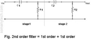
A higher-order filter can be achieved by cascading two or more stages of the filter. These stages of the filter are either schematic of RC or LC. The order of the filter is increased so that we get a very sharp response curve that is near to the Ideal filter. The first-order filter gives a slope of 20 dB/decade.
If we add 2nd stage in series with the first stage then 40 dB/ decade is achieved.
Practical example to design High pass filter:
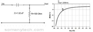
Design a high pass filter fc=1.2 kHz using RC?
Given- fc=1.2kHz
R=100Ω (assumed)
find C using formula: ƒc = 1/(2πRC). And it came out to be 1.32uf

Design a high pass filter having cutoff frequency fc=3 MHz using RC components?
Given- fc=3MHz
R=100Ω (assumed)
find C using formula: ƒc = 1/(2πRC). And it came out to be 0.53nf

Design a high pass filter having cutoff frequency fc=90 MHz using LC components?
Given- fc=90MHz
C=25pf (assumed)
find L using formula:
ƒc = 1/(2π√LC).
And it came out to be ~62nH

What is high pass filter used for? Its applications.
1) While recording audio outdoor using a mic, causes the sound of wind also gets recorded as noise. The frequency of the human voice is slightly higher than that of the noise of the wind.
The sound of the wind is of lower frequencies which are unnecessary, therefore, high pass filter is used to lower the noise.
2) In pre-amplifier to avoid amplification of noise
3) To reduce ‘Hiss’ sound in the audio circuit (caused due to power lines nearby).
4) For Waveshaping in different applications in analog and digital electronics.
5) It is used as differentiator circuit(converts square wave/ step response to spike/impulse)
6) As an audio equalizer, then this filter is called treble boost filters.
Bonus Tips/Overview:
In short, High filter makes it difficult for a low frequency to pass through it and eases high frequency to pass through it.
The trick to identifying whether the filter is a highpass filter or low pass filter?
a) if the position of the capacitor is lower that is a low pass filter (parallel to the input)
b) if the position of the capacitor is upper then it is high pass filter (in series with input)


